LT230Q TRANSFER BOX. Manual - part 14
TRANSFER BOX
OVERHAUL
39
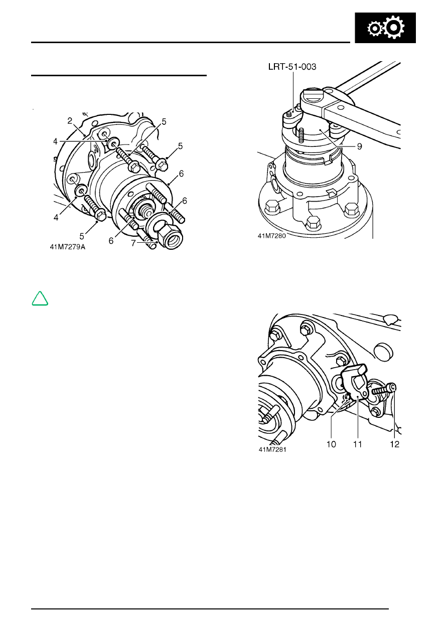
Rear output housing
1. Apply Hylosil RTV 102 sealant to mating flange
of rear output housing.
2. Fit rear output housing to main casing.
NOTE: Dowel located.
3. Apply Loctite 290 to threads of bolts and
shoulder bolt.
4. Fit washers to 2 bolts.
5. Fit bolts and tighten by diagonal selection to 25
Nm (18 lbf.ft).
6. Fit output flange, new felt and steel washers to
output shaft.
7. Fit a new self-locking nut.
8. Position propeller shaft flange holding tool
LRT-51-003 to output flange.
9. Restrain flange, tighten nut to 162 Nm (120
lbf.ft).
10. Lubricate a new ’O’ ring with recommended oil
and fit to vehicle speed sensor - if fitted.
11. Fit vehicle speed sensor - if fitted.
12. Fit and tighten Allen screw.