Land Rover Engine 2.0 Litre L Series. Manual - part 12


  Index      Land Rover     Land Rover Engine 2.0 Litre L Series Diesel - service manual 2000 year


Search            


Content   ..  10  11  12  13   ..


Land Rover Engine 2.0 Litre L Series. Manual - part 12


ENGINE

38

OVERHAUL

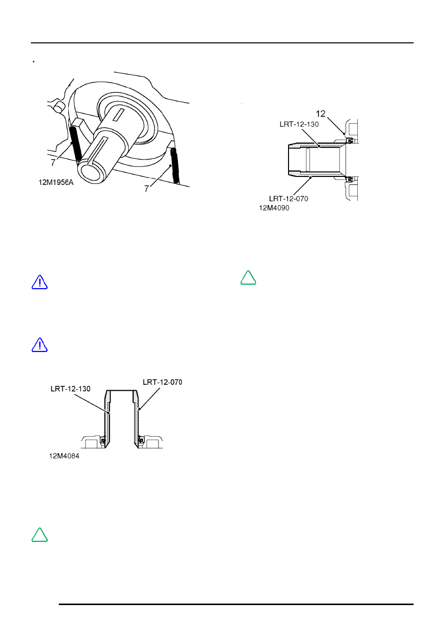
7. Using sealant, Part No. GUG 705963GM,

apply a 1 mm thick bead of sealant to joint line
of front - Number 1 main bearing cap and
cylinder block.

CAUTION: Do not fill grooves on either
side of main bearing cap or apply sealant
to sump mating flange of main bearing

cap until immediately before sump is fitted.

8. Position a new gasket to cylinder block.

CAUTION: Gasket must be fitted dry.

9. Insert oil seal protector LRT-12-070 and

adaptor sleeve LRT-12-130 into oil pump inner
rotor.

NOTE: This will assist in locating oil pump
inner rotor on Woodruff key.

10. Align Woodruff key slots in oil pump inner rotor

with Woodruff key

11. Ensure bolt holes in cylinder block are clean

and dry.

12. Slide oil pump over crankshaft ensuring

Woodruff key is located in keyway in inner
rotor, locate oil pump on dowels.

NOTE: Tools LRT-12-070 and LRT-12-130
will be displaced as pump is fitted.

ENGINE

OVERHAUL

39

13. Fit and lightly tighten bolts ensuring that

longest M6 bolt is fitted at position 1 and M10
bolt at position 9.

NOTE: Patchlok bolts may be re-used
provided threads are undamaged.

14. Gradually tighten bolts in sequence shown until

oil pump is pulled against cylinder block.

CAUTION: Bolt tightening must be done
gradually due to tight fit of pump rotor on
crankshaft. Damage to oil pump will result

if the above procedure is not followed.

15. Finally, tighten bolts in sequence shown to:

M6 bolts - 8 Nm
M10 bolt - 45 Nm

16. Ensure sealing strips are fitted to camshaft

timing belt lower rear cover.

17. Fit lower rear cover, fit and tighten screws to 8

Nm.

18. Fit camshaft timing belt idler pulley ensuring

that recessed side of centre boss faces away
from engine.

19. If idler pulley stud was unscrewed during nut

removal, clean old Loctite from threads of stud
and ensure hole in cylinder block is clean and
dry. Apply Loctite 275 to threads of stud and
screw it into block, tighten stud to 12 Nm.

20. Apply Loctite 275 to threads of idler pulley nut,

fit and tighten nut to 45 Nm.

21. Slide timing gear on to crankshaft.
22. Fit new camshaft timing belt and adjust

tension.

CRANKSHAFT, MAIN AND BIG-END BEARINGS

Crankshaft rear oil seal - remove

1. Remove 5 bolts securing rear oil seal housing

to cylinder block, remove and discard housing
and oil seal.

ENGINE

40

OVERHAUL

Big-end bearings - remove

1. Suitably mark cylinder reference number on

each big-end bearing cap and connecting rod.

2. Remove 2 bolts securing each big-end bearing

cap, remove caps and recover big-end bearing
shells.

NOTE: The big-end bearing shells do not
have location tags for locating the
bearings in the connecting rod and

bearing cap. The big-end to connecting rod bolts
are off-set 1 mm to prevent incorrect fitment of
the bearing cap to the connecting rod.

CAUTION: Keep bolts and bearing caps in
their fitted order. Big-end bearing shells
should always be replaced whenever

crankshaft is removed.

3. Push each connecting rod up cylinder bore

until connecting rod is clear of the crankshaft
journals.

CAUTION: Ensure connecting rods do not
contact oil squirt jets or cylinder bores.

Crankshaft end-float - check

1. Attach a magnetic base Dial Test Indicator to

front of cylinder block, move crankshaft
rearwards, position stylus on end of crankshaft
and zero DTI.

2. Move crankshaft forwards, measure and record

end-float figure obtained:
End-float = 0.03 to 0.26 mm

3. If end-float exceeds above dimension, new

thrust washers must be fitted:
Thrust washer thickness = 2.31 to 2.36 mm

ENGINE

OVERHAUL

41

Crankshaft - remove

NOTE: Crankshaft end-float must be
checked prior to removing crankshaft.

1. Check that identification marks 1 to 5, and the

direction arrows which face towards the front of
the engine are marked on each main bearing
cap.

NOTE: The identification marks on number
2 main bearing cap are concealed by the
oil strainer mounting bracket which is

secured to the bearing cap.

2. Starting at centre main - Number 3 main

bearing cap and working outwards,
progressively loosen, then remove 2 bolts
securing each cap.

CAUTION: Keep bolts in their fitted order.

3. Using fingers only, rock each main bearing cap

until it is released from locating dowels.

CAUTION: Do not tap caps sideways.

4. Remove main bearing caps and plain bearing

shells.

5. Using assistance, remove crankshaft.
6. Recover upper, grooved main bearing shells

and 2 thrust washers.

7. Using a suitable cleaning solvent, remove

sealant from front - Number 1 main bearing
cap and cylinder block.


Content   ..  10  11  12  13   ..