Land Rover Engine 2.0 Litre L Series. Manual - part 6


  Index      Land Rover     Land Rover Engine 2.0 Litre L Series Diesel - service manual 2000 year


Search            


Content   ..  4  5  6  7   ..


Land Rover Engine 2.0 Litre L Series. Manual - part 6


ENGINE

14

OVERHAUL

Camshaft bearings - check clearance

1. Clean all traces of oil from camshaft, cylinder

head and camshaft carrier.

2. Use suitable cleaning solvent and remove all

traces of sealant from cylinder head and
camshaft carrier.

CAUTION: Do not use a metal scraper.

3. Position camshaft in cylinder head.
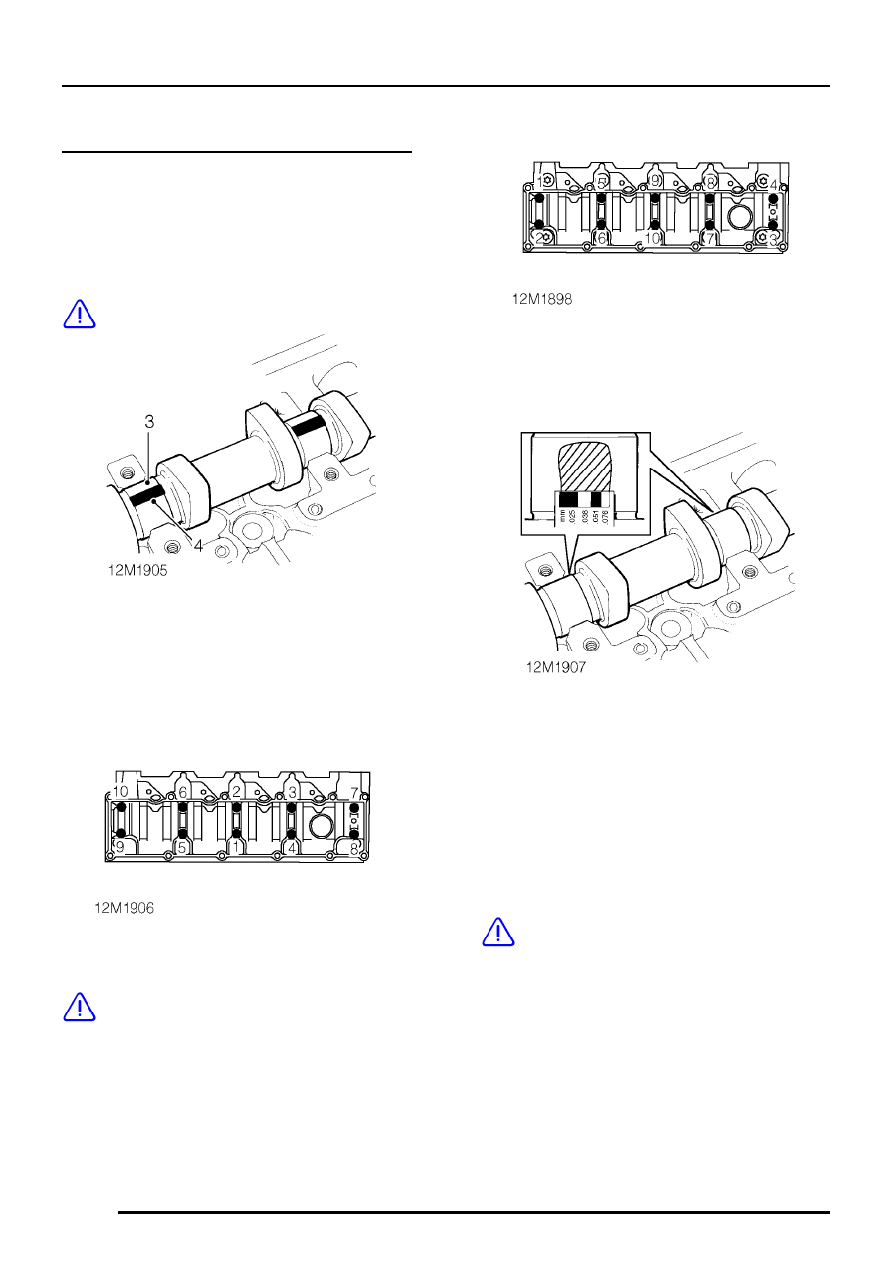
4. Place a piece of Plastigage along the centre

line of each camshaft journal.

5. Support each end of cylinder head on blocks of

wood.

6. Carefully fit the camshaft carrier, fit 10 retaining

bolts and tighten in sequence shown to 11 Nm.

CAUTION: Do not rotate camshaft.

7. Using sequence shown, progressively loosen,

then remove 10 retaining bolts.

8. Carefully remove camshaft carrier.

9. Measure and record widest portion of

Plastigage on each camshaft journal.

10. Compare figures obtained with camshaft

bearing clearance:
Bearing clearance = 0.043 to 0.094 mm

11. If any bearing clearance is found to be

excessive, repeat the above procedure using a
new camshaft.

CAUTION: If, after repeating the bearing
clearance check with a new camshaft the
clearances are still excessive, a new

cylinder head and camshaft carrier assembly
must be fitted.

12. Remove Plastigage using an oily cloth, do not

use a scraper.

ENGINE

OVERHAUL

15

Valve springs - inspection

1. Check valve springs free length:

Free length = 37mm

CAUTION: Valve springs must be replaced
as a set.

Valves and valve guides - inspection

NOTE: Two types of exhaust valve may be
fitted, standard valves - A in illustration or
carbon break valves - B in illustration.

Carbon break valves may be identified by the
machined profile - C on the valve stem. To
prevent valves from sticking, standard valves
should be replaced with carbon break valves
during engine overhaul.

1. Clean carbon from valves, check valves for

burning, pitting or cracking; replace as
necessary.

2. Remove carbon deposits from valve guides

using tool 12-186.

CAUTION: Tool must be inserted from
combustion chamber face side of cylinder
head.

3. Remove carbon from valve seat inserts;

remove all loose particles of carbon on
completion.

ENGINE

16

OVERHAUL

4. Check and record diameter of each valve stem,

replace any valve if diameter is less than
specified.
Inlet = 6.907 to 6.923 mm.
Exhaust = 6.897 to 6.913 mm.

5. Check inlet and exhaust valve to guide

clearances using the following procedures:

6. Insert a valve into its respective guide.
7. Extend valve out of seat by 10 mm.
8. Position a DTI gauge on to rear side of valve

head. Move valve towards front of cylinder
head, pre-load gauge to valve head and zero
gauge. Move valve towards rear of cylinder
head, record gauge reading obtained to give
valve stem to guide clearance.

9. Repeat above procedures for remaining

valves.
Maximum valve to guide clearance:
Inlet valve = 0.056 mm.
Exhaust valve = 0.066 mm

10. Renew any guide and its associated valve if

movement/clearance is excessive.

Valve guides - renew

1. Check area on camshaft side of cylinder head

around valve guide to be replaced for marks
denoting previous valve guide replacement:
+ denotes 1st replacement
- denotes 2nd replacement

CAUTION: Valve guides may only be
replaced twice.

2. Heat cylinder head uniformly to a temperature

of 120

°

C.

WARNING: Take care when handling hot
cylinder head.

3. Using a suitable pilotted mandrel, press valve

guide out of cylinder head from combustion
face side; discard guide.

NOTE: Only one size of replacement guide
is available.

4. Reheat cylinder head to 120

°

C.

ENGINE

OVERHAUL

17

5. Using the pilotted mandrel, press replacement

valve guide into cylinder head from camshaft
side of head until fitted height of guide from
combustion face side of cylinder head to top of
guide is 61.1 to 61.7 mm

6. Allow cylinder head to air cool.
7. Ream bores of replacement valve guide

ensuring that reamer is kept perpendicular to
and concentric with valve seat.
Valve guide bore diameter = 6.950 to 6.963
mm

CAUTION: If valve seat insert has also
been replaced, guide and insert must be
machined together.

8. Suitably mark cylinder head on camshaft side

of head to denote that guide has been
replaced.
1st replacement guide +
2nd replacement valve guide -

CAUTION: A new valve must always be
fitted whenever a guide is replaced.

Valve seat inserts and valves - refacing and
lapping-in

Refacing valve seat inserts

1. Check valve seat inserts for pitting and

burning, if necessary, valve seats may be
refaced providing valve head stand down is
within limits after refacing.

2. Using valve seat cutter pilot MS 76, and a

60

°

cutter, tool MS 76-111, cut valve seat insert

to correct angle and width:

Inlet valve seat insert:
Seat width A = 35.697 mm
Seat angle B = 60

°

Exhaust valve insert:
Seat width A = 31.05 to 31.55 mm
Seat angle B = 58

°

to 62

°


Content   ..  4  5  6  7   ..