Land Rover Engine 2.0 Litre T Series. Manual - part 10


  Index      Land Rover     Land Rover 2.0 Litre T Series Engine - service manual 1997 year


Search            


Content   ..  8  9  10  11   ..


Land Rover Engine 2.0 Litre T Series. Manual - part 10


ENGINE

OVERHAUL

25

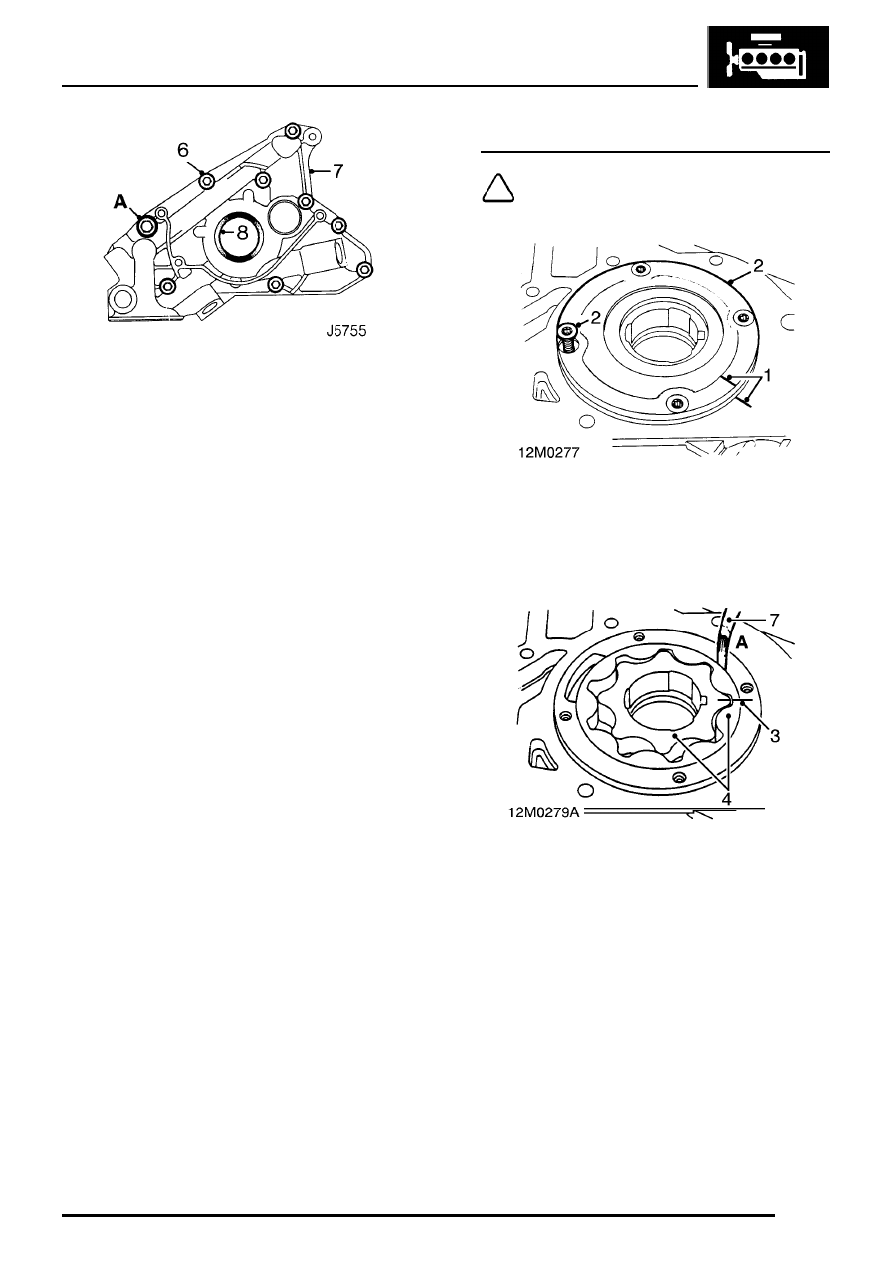
6. Noting fitted position of M10 x 20 bolt A,

remove 9 bolts securing oil pump to cylinder
block.

7. Slide oil pump off crankshaft, discard gasket.
8. Carefully prise crankshaft front oil seal out of

oil pump body; discard oil seal.

Oil pump - inspection

NOTE: The oil pump is serviced as an
assembly. The following checks can be
carried out to determine serviceability.

1. Make suitable alignment marks between oil

pump body and cover plate.

2. Remove 4 Torx screws securing cover plate,

remove plate.

3. Using a felt tipped pen, make suitable

alignment marks between inner and outer
rotors and oil pump body.

4. Remove inner and outer rotors.
5. Check rotors and oil pump body for signs of

wear and scoring.

6. Fit rotors ensuring that reference marks are

aligned and chamfered side of outer rotor
carrying a square identification mark is facing
away from backplate side of pump body.

7. Check outer rotor to body clearance:

Clearance = 0.05 to 0.10 mm

ENGINE

26

OVERHAUL

8. Check inner rotor lobe tip clearance:

Clearance = 0.025 to 0.12 mm

9. Check outer rotor end float:

End float = 0.03 to 0.08 mm
Renew oil pump assembly if clearances are
excessive or scoring of components is evident.

Oil pressure relief valve

1. Remove and discard split pin securing relief

valve cap.

2. Remove relief valve cap, spring and plunger,

discard relief valve cap ’O’ ring.

3. Check that plunger is not scored and slides

freely in bore.

4. Check that bore is free from corrosion.

NOTE: Light corrosion may be removed
using grade 600 emery cloth soaked in
engine oil.

5. Check free length of spring:

Spring free length = 38.9 mm

Renew relief valve as an assembly if scoring of
plunger is evident or free length of spring is less
than specified.

ENGINE

OVERHAUL

27

Oil pump - assembling

1. Clean relief valve components and ensure bore

in oil pump body is clean.

2. Using suitable solvent, gasket removal spray

and plastic scraper, remove all traces of
sealant and gasket from oil pump and cover
plate.

3. Remove all traces of Loctite from Torx screws

and tapped holes in oil pump body; ensure
holes are clean and dry.

CAUTION: Do not use a tap.

Oil pressure relief valve

4. Smear a new ’O’ ring with engine oil and fit to

relief valve cap.

5. Lubricate spring, plunger and bore in oil pump

body with engine oil.

6. Fit plunger, spring and relief valve cap; secure

assembly with a new split pin.

Oil pump

7. Lubricate rotors with engine oil.
8. Fit rotors ensuring that reference marks are

aligned and chamfered side of outer rotor
carrying a square identification mark is facing
away from backplate side of pump body.

9. Apply a 1 mm bead of Loctite 573 to cover

plate as shown.

10. Apply Loctite 222 to threads of Torx screws.
11. Fit cover plate ensuring reference marks are

correctly aligned.

12. Fit Torx screws and tighten in diagonal

sequence to 6 Nm.

13. Check that pump rotates freely.

ENGINE

28

OVERHAUL

Oil pump - refit

1. Using gasket removal spray and plastic

scraper, remove all traces of gasket from
cylinder block.

2. Using suitable solvent, remove sealant from

front main bearing cap,

3. Ensure 2 oil pump locating dowels are in

position.

4. Remove all traces of Loctite from threads of oil

pump securing bolts and bolt holes. Ensure
bolt holes are clean and dry.

5. Clean timing belt lower cover backplate.
6. Position a new gasket to oil pump body.

7. Apply a 1.0 mm bead of sealant from kit, Part

Number GUG 705548GM to vertical joint of
front main bearing cap.

NOTE: Main bearing caps fitted to later
engines have a groove machined along
either side of sump mating face, do not fill

the side grooves with sealant until sump is fitted.

8. Insert oil seal protector sleeve LRT-12-070

into oil pump inner rotor; this will assist in
locating oil pump inner rotor on Woodruff key.

9. Align Woodruff key slot in oil pump inner rotor

with crankshaft Woodruff key.

10. Slide oil pump over crankshaft ensuring

Woodruff key is located in keyway in inner
rotor.

11. Locate oil pump on dowels; oil seal protector

sleeve LRT-12-070 will be displaced as pump
is fitted.

12. Apply Loctite 222 to threads of oil pump

securing bolts.


Content   ..  8  9  10  11   ..