Range Rover Classic. Manual - part 154
CHASSIS AND BODY
39
REPAIR
7. Pull door seal away to remove lower ’B’ post
trim.
8. Remove seat belt through slot in lower ’B’ post
trim.
9. Remove bolt and spring washer from inertia reel
assembly to ’B’ post.
10. Disconnect electrical plug and remove bolt
securing buckle to seat base.
Refit
11. Reverse removal procedure. Ensure belts are
not twisted. Tighten bolts to
25Nm.
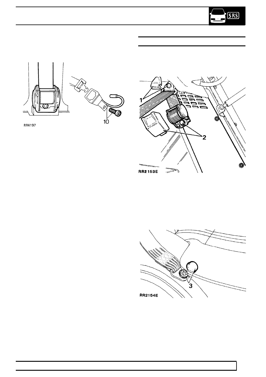
REAR SEAT BELT
Service repair no - 76.73.18
Remove
1. Remove plastic cover from upper guide bracket.
Remove bolt, spacer, plain and wavy washer.
2. Unclip cover from inertia reel assembly. Remove
bolt, spring washer. Place reel to one side.
3. Remove plastic cover and bolt securing belt
assembly to wheel arch.
4. Remove belt assembly.