Range Rover Classic. Manual - part 151


  Index      Land Rover     Range Rover Classic - service manual 1995 year


Search            


Content   ..  149  150  151  152   ..


Range Rover Classic. Manual - part 151


CHASSIS AND BODY

27

REPAIR

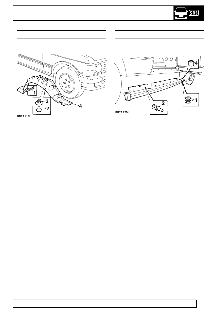
FRONT WHEEL ARCH LINER

Service repair no - 76.10.48

Remove

1. Remove bolt and washer securing rear lower

edge of liner.

2. Pry out centre studs of eight plastic clips spaced

around liner.

3. Pry out plastic clips.
4. Remove liner.

Refit

5. Reverse removal procedure. Renew clips as

necessary.

SILL FINISHER

Remove

1. Remove nut and washer from underneath front

of sill finisher.

2. Tap out centre piece of ten Rocut fixing rivets.
3. Pry out Rocut rivets and remove sill finisher.

Refit

4. Reverse removal procedure. Renewing Rocut

rivets. Ensure metal tube insert is refitted into sill
finisher where bolt goes through.

76

CHASSIS AND BODY

28

REPAIR

REAR DOOR

Service repair no - 76.28.06

Remove

1. Disconnect battery negative lead.

2. Remove wiring grommet from ’B’ post.
3. Withdraw door wiring plugs from ’B’ post and

disconnect.

4. Remove two bolts securing the check strap to ’B’

post.

5. Remove ’C’ clips from grooves in hinge pins.

WARNING: Instruction 6. MUST BE carried
out with assistance.

6. Lift opened door off hinge pins.

Refit

7. Reverse removal procedure. Renew ’C’ clips if

worn or distorted.

Adjust

8. Adjust door by means of shims between hinge

and door to move door forward or rearward in
the opening.

9. Loosen six screws securing hinges to door to

adjust door up and down or in and out of
opening. Retighten screws to

25Nm.

10. Adjustment to door striker is identical to front

doors.

11. Note: If it is necessary to remove hinges from ’B’

post they should be refitted in exact same
position using same thickness of shims.

CHASSIS AND BODY

29

REPAIR

REAR DOOR - TRIM PANEL

Service repair no - 76.34.04/98

Remove

1. Disconnect battery negative lead.

2. Remove screw securing handle surround.
3. Remove surround.
4. Pry door locking button surround from trim panel.

5. Remove two finisher buttons from door pull

pocket to reveal securing screws.

6. Remove screws and withdraw pocket.
7. Pry trim panel away from door.
8. Disconnect electrical plug from window lift

switch.

9. Remove window lift switch.

Refit

10. Reverse removal procedure.

76

CHASSIS AND BODY

30

REPAIR

REAR DOOR LOCK, OUTSIDE AND INSIDE DOOR
RELEASE HANDLES

Service repair no - 76.37.13

Remove

1. Fully close window.
2. Disconnect battery negative lead.
3. Remove trim panel.

See Rear Door - Trim

Panel

4. Remove plastic vapour barrier sheet.
5. Disconnect inside door release control rod from

door lock.

6. Disconnect sill locking control rod from door lock

by releasing metal clip.

7. Disconnect control rod from outside door release

handle by pulling it out of plastic olive.

8. Remove door lock by removing two screws from

door shut face and single screw with shakeproof
washer on inside of door. Retrieve any spacing
washers which may be fitted.

9. Remove lock through upper rear opening of

panel.

10. Remove two nuts with shakeproof washers and

retaining bracket securing outside door release
handle.

11. Remove outside door release handle from outer

door panel.

12. Remove two screws with plain washers securing

inside door release handle to inner door panel.

13. Remove handle with connecting rod attached.
14. Remove two screws securing sill locking button

to inner door panel and detach sill button from
bellcrank.

Sill locking bellcranks

15. Press out plastic locking pins from inner door

panel.

16. Release bellcranks from inner door panel and

unhook respective connecting rods.

17. Withdraw bellcranks from inner door panel.

NOTE: When fitting bellcranks, locking
pins are entered into square insert from
outside and pressed in flush.

Refit

18. Reverse removal procedure. 1 to 17.


Content   ..  149  150  151  152   ..