Range Rover Classic. Manual - part 139
 

  Index      Land Rover     Range Rover Classic - service manual 1995 year


Search            


Content   ..  137  138  139  140   ..


Range Rover Classic. Manual - part 139


75

SUPPLEMENTARY RESTRAINT SYSTEM

2

FAULT DIAGNOSIS

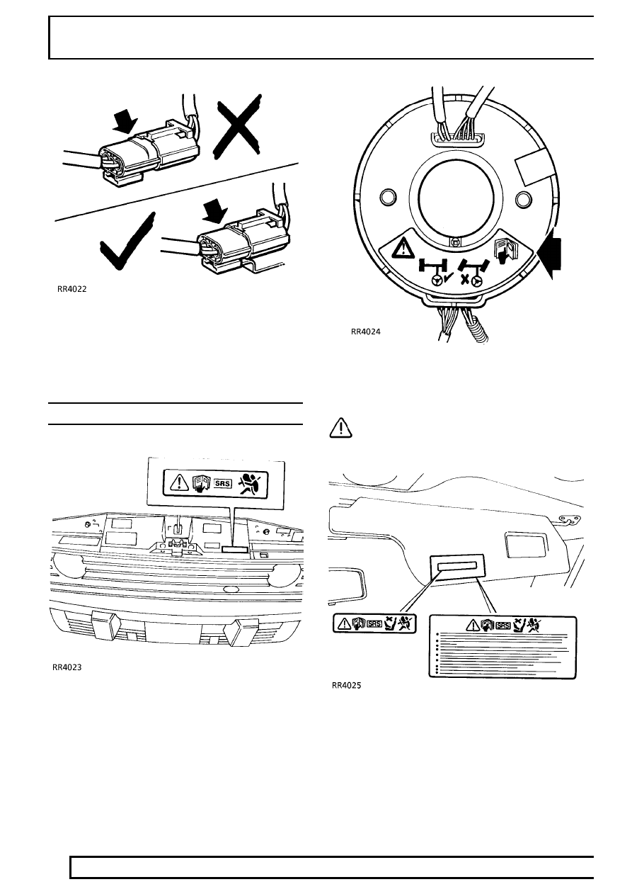
3. Ensure all airbag harness connectors are mated

correctly and securely fastened. Do not leave the
connectors hanging loose.

WARNING LABELS

1. Bonnet locking platform

Refer to the Owner’s Handbook for information on the
airbag system.

2. Rotary coupler

CAUTION: Ensure wheels are straight
ahead before removal and installation.

3. Driver’s sun visor

Refer to the Owner’s Handbook for information on the
airbag system.

SUPPLEMENTARY RESTRAINT SYSTEM

3

FAULT DIAGNOSIS

4. Airbag modules

- If defective, replace and dispose of the entire unit
as directed in the instructions. Under no
circumstances should a diagnosis be performed using
electrically powered test equipment or probing
devices.

- Tampering or mishandling can result in personal
injury. For special handling instruction refer to the
Workshop manual. This airbag module cannot be
repaired. Use diagnostic instructions to determine if
the unit is defective.

- ROVER Bar code - The code number must be
recorded if the airbag module is to be replaced.

5. Steering wheel

Refer to the Owner’s Handbook for information
on the airbag system.

SUPPLEMENTARY RESTRAINT SYSTEM

1

REPAIR

SYSTEM PRECAUTIONS

CAUTION: Before and during any removal
operations within the SRS section, note
routing and position of all harnesses to aid

correct refitting and to avoid accidentally trapping
cables.

CAUTION: During refitting of any item
within the SRS section, always ensure
connectors are fully engaged and latched

before proceeding to the next stage of the
operation.

DRIVER’S AIRBAG MODULE

Service repair no - 76.74.01

WARNING: All the airbag system
components, including the wiring harness,
MUST be renewed after the airbags have

deployed.

Remove

1. Turn steering wheel 90˚ from horizontal.
2. Switch off ignition.
3. Disconnect battery negative ’-’ and then the

positive ’+’ lead.

CAUTION: Always disconnect both leads.

4. Release 2 turnbuckles and remove dash lower

panel.

5. Disconnect airbag harness connector from

yellow airbag column harness.

6. Use special socket, unscrew 2 tamper-proof

Resistorx screws securing airbag module to
steering wheel.

7. Release airbag module from steering wheel.

CAUTION: Do not allow the airbag module
to hang by the airbag harness.

75

SUPPLEMENTARY RESTRAINT SYSTEM

2

REPAIR

8. Disconnect harness connector from airbag

module.

9. Remove airbag module.

CAUTION: Store the airbag module in
accordance with the storage procedures
outlined in Description and Operation.

NOTE: If airbag module is to be replaced
the serial numbers must be recorded in
the vehicle service record.

Refit

10. Reverse removal procedure.
11. Connect harness connector to airbag module

with harness downwards (as shown at 8).

12. Position airbag module on steering wheel and

engage retained screws. Use special socket to
tighten screws to

8Nm.

CAUTION: Take care not to cross thread
screws.

13. Check Supplementary Restraint System using

Testbook .

STEERING WHEEL

Service repair no - 57.60.01

Remove

1. Remove driver’s airbag module.

See Driver’s

Airbag Module

2. Position steering wheel so the road wheels are

in the straight ahead position.

3. Disconnect cruise control switch connector

(where fitted) from rotary coupler harness.

4. Release harnesses from clip on steering wheel.
5. Remove steering wheel nut.
6. Release steering wheel from column.
7. Feed harnesses through hole in steering wheel.
8. Remove steering wheel.

CAUTION: Prevent rotation of rotary
coupler once steering wheel is removed.
Secure in position with adhesive tape.

Refit

9. Reverse removal procedure.

CAUTION: Ensure road wheels are straight
ahead before fitting steering wheel.

10. Fit steering wheel ensuring the rotary coupler

lugs are correctly engaged.

11. Fit steering wheel nut. Tighten to

50Nm.

12. Refit driver’s airbag module.

See Driver’s

Airbag Module


Content   ..  137  138  139  140   ..