Range Rover Classic. Manual - part 127


  Index      Land Rover     Range Rover Classic - service manual 1995 year


Search            


Content   ..  125  126  127  128   ..


Range Rover Classic. Manual - part 127


BRAKES

15

REPAIR

Assemble outboard pistons

13. Coat new fluid seal with brake fluid. Ease seal

into groove in bore using only fingers, ensuring it
is properly seated. Fluid seal and groove are not
same in section, so when seal is seated it feels
raised to touch at edge furthest away from
mouth of bore.

14. Coat appropriate piston with brake fluid. Insert it

squarely into bore by hand only. Do not tilt piston
during insertion, leave approximately 8mm
projecting from bore.

15. Coat new wiper seal with brake fluid and fit to

new seal retainer. Slide assembly, seal first, over
protruding piston and into bore recess. Use
piston clamp to press home seal retainer and
piston.

Mounting inboard pistons

16. Clamp outboard pistons and carry out same

procedure for removing and fitting outboard
pistons and seals, instructions 8 to 15.

Fit calipers and pads

17. Fit caliper, tighten bolts progressively to,

82 Nm.

18. Connect brake flexible hoses to caliper. Tighten

to

10 Nm.

19. Remove hose clamps.
20. Lightly coat back and edges of pads with brake

fluid, avoid friction material.

21. Insert pads. Fit pins and springs, secure using

new split pins.

NOTE: Ensure friction pad with wear
indicator is fitted to inboard side of front
RH caliper. New pads must be fitted to

each caliper.

22. Reconnect pad wear indicator plug.
23. Bleed brake system.

See Brake System Bleed

(non ABS)

24. Press brake pedal firmly several times to locate

friction pads.

25. Fit road wheels, remove axle stands. Finally

tighten road wheel nuts.

26. Road test vehicle. Note that new friction pads

require ’bedding-in’, this may take several
hundred miles before brakes are at maximum
efficiency.

REAR BRAKE CALIPERS

Service repair no - 70.55.06
Service repair no - 70.55.17

Service tool:
LRT-50-700 - Piston clamp

Remove caliper

1. Loosen rear road wheel nuts. Jack up vehicle,

lower onto axle stands, remove wheels.

2. Using a recognised hose clamp, clamp flexible

brake hose above rear axle.

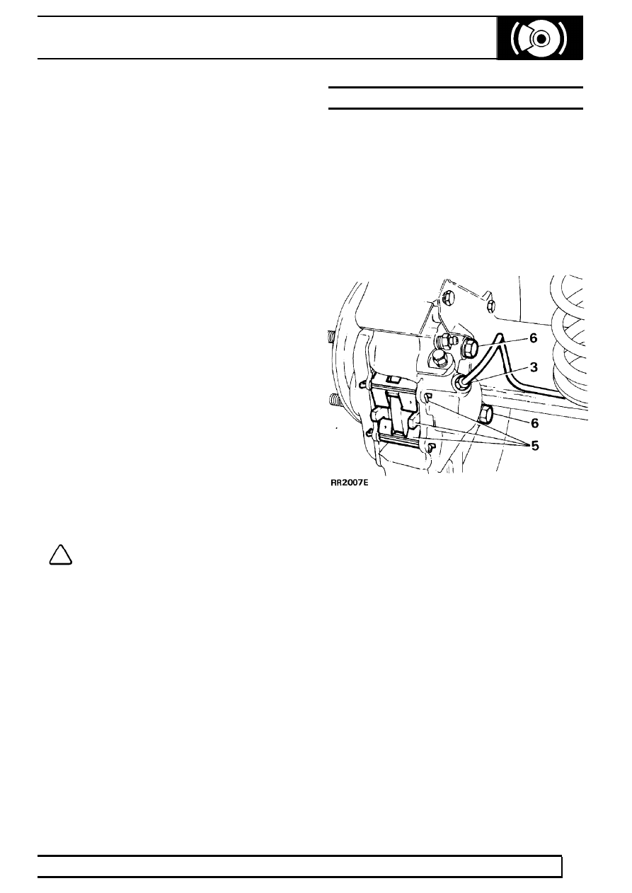
3. Remove brake pipe(s) from rear brake caliper(s).

Seal pipe ends to prevent ingress of dirt.

4. Rear RH caliper only, disconnect pad wear

indicator.

5. Remove retaining pins and springs and withdraw

pads. If same pads are to be refitted, identify
them for assembly in original positions.

6. Remove two bolts, withdraw caliper from axle.

70

BRAKES

16

REPAIR

DISMANTLE AND REPAIR

CAUTION: Do not separate caliper halves.
Overhaul both calipers

7. Clean outer surfaces of caliper with aerosol

brake cleaner.

8. WITH CAUTION expel pistons from their bores

by applying air pressure to fluid inlet port. It is
unlikely both pistons will expel at same time,
regulate rate with a suitable piece of wood
inserted between two pistons.

9. Finally, remove pistons keeping them identified

with their respective bores.

10. Remove wiper seal retainer by inserting a blunt

screwdriver between retainer and seal and pry
retainer carefully from mouth of bore.

11. Taking care not to damage seal grooves, extract

wiper seal and fluid seal.

12. Clean bores, pistons and particularly seal

grooves using clean brake fluid only. If caliper or
pistons are corroded or their condition is not
perfect new parts must be fitted. Assemble
outboard pistons.

13. Coat a new fluid seal using brake fluid. Ease

seal into groove in bore using only fingers and
ensure that it is properly seated. The fluid seal
and groove are not same in section so that when
seal is seated it feels raised to touch at edge
furthest away from mouth of bore.

14. Coat appropriate piston with brake fluid. Insert it

squarely into bore by hand only. Do not tilt piston
during insertion and leave approximately 8mm
projecting from bore.

15. Coat a new wiper seal with brake fluid and fit to

new seal retainer. Slide assembly, seal first, over
protruding piston into bore recess.

16. Using special tool LRT-70-500 - piston clamp,

press home seal retainer and piston.

Mounting inboard piston

17. Carry out same procedure as for removing and

fitting outboard piston and seals, instructions 8 to
16.

Fit calipers and pads to vehicle

18. Fit caliper to axle, tighten two bolts progressively

to

82Nm.

19. Connect brake pipe to caliper. Tighten to

12Nm.

Remove clamp from flexible brake hose.

20. Lightly coat back and edges of pads using brake

fluid, avoid friction material.

21. Insert pads and retaining springs, secure in

position with new retaining pins and spread
ends. Note correct position of retaining springs.

NOTE: Ensure pad with wear indicator is
fitted to inboard side of rear RH brake
caliper. New brake pads must be fitted to

each caliper.

22. Reconnect pad wear indicator electrical plug.
23. Bleed secondary brake system at rear calipers,

starting at caliper furthest away from master
cylinder.

24. Press brake pedal firmly several times to locate

pads.

25. Fit road wheels, remove axle stands and finally

tighten road wheel nuts,

26. Road test vehicle. Note new brake pads require

’bedding-in’, for several hundred miles before
brakes are at maximum efficiency.

BRAKES

17

REPAIR

PARKING BRAKE LEVER

Service repair no - 70.45.01

Remove

1. Disconnect battery negative lead.
2. Chock road wheels and release parking brake.
3. Remove centre console assembly.

See

CHASSIS AND BODY, Repair, Centre
Console

4. Remove spring clip and clevis pin.
5. Disconnect parking brake cable from lever.
6. Raise parking brake lever fully.
7. Disconnect electrical lead from parking brake

warning switch.

8. Release parking brake cable outer retaining nut.
9. Remove 2 bolts securing parking brake

mounting bracket.

10. Remove parking brake lever assembly from

parking brake outer cable.

Refit

11. Position parking brake lever over parking brake

cable and secure in position.

12. Secure parking brake outer cable to mounting

plate, tighten nut securely.

13. Reverse removal procedure. Ensure electrical

wiring does not become trapped between mating
faces.

14. Check parking brake adjustment.

See SECTION

10, Maintenance, Vehicle Interior

STOP LIGHT SWITCH - NON ABS

Service repair no - 86.65.51

Remove

1. Disconnect battery negative lead.
2. Remove lower dash panel.
3. Depress foot brake.
4. Remove rubber protector from switch, if fitted.
5. Remove hexagon nut.
6. Withdraw switch.
7. Disconnect electrical leads.

Adjust

8. With switch still in position and multiplug

disconnected, connect an ohmmeter across
switch terminals.

9. Screw switch in until open circuit exists across

terminals with pedal released and continuity
exists as soon as pedal is depressed.

10. Tighten locknut.

CAUTION: Ensure switch does not prevent
brake pedal returning fully.

Refit

11. Reverse removal procedure.

70

BRAKES

18

REPAIR

REAR BRAKE CALIPER ASSEMBLY

LH Rear Caliper illustrated

Key to caliper

1. Caliper
2. Bleed screw
3. Pad retaining springs
4. Brake pads
5. Piston

6. Wiper seal retainer
7. Wiper seal
8. Fluid seal
9. Retaining pins


Content   ..  125  126  127  128   ..