Range Rover Classic. Manual - part 80


  Index      Land Rover     Range Rover Classic - service manual 1995 year


Search            


Content   ..  78  79  80  81   ..


Range Rover Classic. Manual - part 80


44

AUTOMATIC GEARBOX

22

REPAIR

REPLACING INTERMEDIATE PLATE

Service repair no - 44.20.11

1. Remove gearbox and transfer box assembly.

See ZF Auto with Borg Warner Transfer
Gearbox

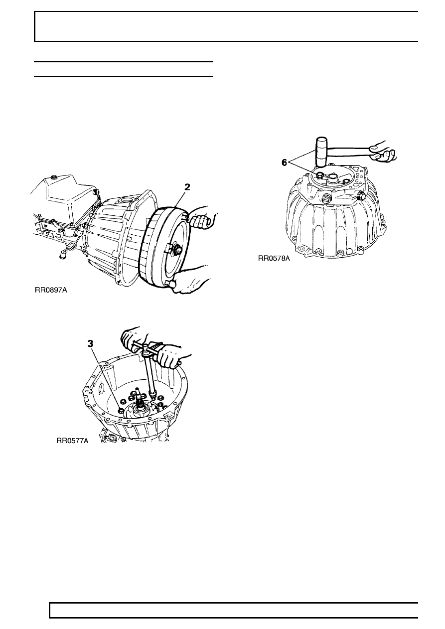
2. Place gearbox on bench. Remove torque

converter using torque converter handles
18G1501.

3. Remove twelve bolts (inner ring pattern).

4. Remove bell housing and pump assembly from

gearbox case, discard gasket.

5. Remove eight bolts from rear of pump.
6. Screw in two bolts, diagonally opposite each

other, tap pump to free pump assembly from
intermediate plate.

7. Remove ’O’ ring from pump housing and

discard.

8. Place bell housing and intermediate plate

assembly on bench.

ZF

23

REPAIR

9. Remove six bolts and remove bell housing from

intermediate plate assembly.

10. Remove four screw plugs and seal rings from

intermediate plate, discard seal rings.

11. Remove oil cooler pipe adaptors, fit them into

new intermediate plate.

12. Fit plugs and new seal rings into new

intermediate plate.

13. Fit intermediate plate assembly onto bell

housing.

14. Secure with six hexagonal bolts (outer ring

pattern). Tighten to

46 Nm.

15. Place intermediate plate and bell housing

assembly on bench, front face up.

16. Fit ’O’ ring onto circumference of pump housing.
17. Align dowel with hole in intermediate plate, press

pump housing home.

18. Secure pump housing to intermediate plate,

tighten eight bolts to

10Nm.

19. Place bell housing and intermediate plate

assembly on bench. Using oil pump rotation
sleeve LST111, check that pump gears rotate
freely.

20. Before replacing intermediate plate and bell

housing assembly check that thrust washer and
axial cage are seated on ’A’ clutch housing.

21. Place gasket and disc washer onto bell housing

and intermediate plate assembly using
Petroleum Jelly.

22. Fit bell housing and intermediate plate assembly

onto gearcase, tighten twelve bolts to

46 Nm.

23. Place end-float gauge LST111 on pump housing

and check that axial play is between 0,2-0,4 mm.
Renew existing washer, at rear of intermediate
plate, to give required end-float.

24. Refit torque converter into housing using torque

converter handles 18G1501. Check dimension
from converter fixing boss to converter housing
face is 50 mm. This shows converter is properly
seated in housing.

25. Refit gearbox/transfer box assembly.

See ZF

Auto with Borg Warner Transfer Gearbox

ZF

1

SPECIFICATIONS, TORQUE

TORQUE VALUES

NOTE: Torque wrenches should be regularly checked for accuracy to ensure that all fixings are
tightened to the correct torque.

Nm

Coupling shaft to mainshaft

42*

......................................................................

Filler tube to sump

68

.....................................................................................

Gear change lever to gearbox

25

...................................................................

Cooler pipe adaptor to gearbox

42

.................................................................

Securing screws - clutch F

10

.........................................................................

Securing screw - parking pawl

10

...................................................................

Securing screws - pump

10

............................................................................

Intermediate plate plugs (M20)

50

..................................................................

Intermediate plate plugs (M14)

40

..................................................................

Bell housing mounting bolts

46

.......................................................................

Governor mounting screws

10

........................................................................

Extension housing bolts

23

.............................................................................

Control unit mounting bolts

8

.........................................................................

Sump plug

10

..................................................................................................

Mounting screws for sump

8

..........................................................................

Drive plate to converter

39*

.............................................................................

Gearbox to engine

42

.....................................................................................

Strut (threaded end)

42

...................................................................................

Bottom cover to converter housing

9

.............................................................

Cover - converter housing

9

...........................................................................

Drive plates to crankshaft adaptor

40*

............................................................

Adaptor to crankshaft

84

.................................................................................

NOTE: * These bolts must have threads coated with Loctite 270 prior to assembly.

Torque values below are for all screws and bolts used except for those that are specified otherwise.

METRIC

Nm

M5

6

......................................................................................................

M6

9

......................................................................................................

M8

25

.....................................................................................................

M10

45

...................................................................................................

M12

90

...................................................................................................

M14

105

..................................................................................................

M16

180

..................................................................................................

UNC / UNF

1/4

9

......................................................................................................

5/16

24

...................................................................................................

3/8

39

.....................................................................................................

7/16

78

...................................................................................................

1/2

90

.....................................................................................................

5/8

136

....................................................................................................

44

AUTOMATIC GEARBOX

2

SPECIFICATIONS, TORQUE

ZF GEARBOX DATA

Axial end float 0.2 to 0.4 mm.

From torque converter boss to torque converter
housing face 50 mm

Freewheel cage assembly to ring gear; minimum
clearance 0.1 mm

Output shaft above cylinder F assembly; dimension
10.00 mm

A cylinder protrusion above gearbox front face not
more than 8.5 mm


Content   ..  78  79  80  81   ..