Range Rover Classic. Manual - part 29


  Index      Land Rover     Range Rover Classic - service manual 1995 year


Search            


Content   ..  27  28  29  30   ..


Range Rover Classic. Manual - part 29


V8i

3

REPAIR

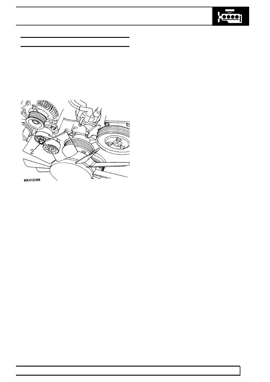
DRIVE BELT TENSIONER

Service repair no - 86.10.09

Remove

1. Remove drive belt from tensioner.

See Drive

Belt Renew

2. Loosen tensioner centre bolt.
3. Remove bolt and tensioner.

Refit

4. Reverse removal procedure.

12

ENGINE

4

REPAIR

CYLINDER HEAD GASKETS - RENEW

Service repair no - 12.29.01

1. Drain cooling system.

See COOLING SYSTEM,

Adjustment, Coolant

2. Remove inlet manifold.

See FUEL SYSTEM,

Repair, Intake Manifold

3. Remove generator.
4. If fitted, remove compressor.

See AIR

CONDITIONING, Repair, Compressor

5. Remove rocker shafts.

See Rocker Shaft

Renew

6. Remove push rods.
7. Remove both exhaust manifolds.

See

MANIFOLD AND EXHAUST SYSTEM, Repair,
Exhaust Manifold - V8i

8. Remove air cleaner assembly.

See FUEL

SYSTEM, Repair, Air Cleaner Assembly

9. Remove air flow sensor.

See FUEL SYSTEM,

Repair, Air Flow Sensor

10. Remove ground leads from rear of left hand

cylinder head

11. Right hand cylinder head - remove breather pipe

from lifting bracket.

12. Loosen cylinder head bolts, reversing tightening

sequence.

13. Remove cylinder heads.
14. Remove cylinder head gaskets.
15. Clean exhaust mating faces.
16. Clean head and block faces.
17. Fit new cylinder head gaskets, word TOP

uppermost. DO NOT use sealant.

18. Oil cylinder bores.
19. Clean threads of head bolts and lightly oil.
20. Locate cylinder heads on block.
21. Locate cylinder head bolts in position illustrated.

96 mm long bolts - 2, 4, 6, 7, 8, 9, 10
66 mm long bolts - 1, 3, 5

NOTE: There are no bolts fitted in the four
lower holes in each cylinder head.

NOTE: Left hand cylinder head illustrated,
arrow points to front of vehicle.

22. Tighten bolts progressively in sequence, shown

to

20 Nm then a further 180˚ æ 5˚

23. Reverse removal procedure. 1 to 11.

V8i

5

REPAIR

CYLINDER HEADS - RENEW

Service repair no - 12.29.15

1. Remove cylinder heads and gaskets.

See

Cylinder Head Gaskets - Renew

2. Remove spark plugs.
3. Using spring compressor LRT-12-034, remove

seals, valves, collets, springs and caps.

CAUTION: Keep components in fitted
order

4. From left hand cylinder head, remove earth lead

studs.

5. Remove three bolts securing power steering

pump mounting bracket to cylinder head.

6. Remove four bolts securing generator mounting

bracket to cylinder head.

7. Right hand cylinder head, remove rear lifting

bracket.

8. Fit lifting bracket to new right hand cylinder

head.

9. Fit mounting brackets and earth lead studs to

new cylinder head. Tighten bolts to

30 Nm.

10. Regrind valves- refer to engine overhaul

publication

11. Lubricate valve stems, fit valves, springs, and

caps. Fit new inlet and exhaust valve stem seals.

12. Using spring compressor LRT-12-034, compress

springs, fit collets. Tap valve to check correct
collet seating.

13. Fit spark plugs.
14. Fit cylinder heads with new gaskets.

See

Cylinder Head Gaskets - Renew

ROCKER COVER - RIGHT HAND - RENEW

Service repair no - 12.29.41

1. Disconnect battery negative lead.
2. Disconnect purge pipe from charcoal canister at

plenum.

3. Remove breather pipe from rocker cover.
4. Remove coolant pipes from inlet manifold.
5. Remove spark plug leads from plugs and

retaining clips.

6. Remove four rocker cover bolts. Moving fuel

pipes aside, remove rocker cover.

7. Discard rocker cover gasket.
8. Remove plug lead retaining clips from rocker

cover, fit to new rocker cover.

9. Clean and dry rocker cover and cylinder head

mating faces, using Bostik cleaner 6001.

NOTE: Gasket fits one way round only. It
must be fitted accurately, first time.
Subsequent movement will destroy

bonding.

10. Apply Bostik 1775 impact adhesive to rocker

cover seal face and gasket, using a brush to
ensure an even film. Allow adhesive to become
touch dry.

12

ENGINE

6

REPAIR

11. Place one end of gasket into cover recess with

edge firmly against recess wall, holding
remainder of gasket clear. Work around cover,
pressing gasket into place ensuring edge firmly
contacts recess wall.

12. Allow cover to stand for thirty minutes before

fitting.

13. Fit rocker cover to cylinder head with four

screws, short screws inboard, tighten to

9 Nm.

14. Position fuel pipes.
15. Fit breather pipe to rocker cover, tighten clip.
16. Fit coolant pipes to inlet manifold, tighten bolts.
17. Fit spark plug leads to plugs and retaining clips.
18. Connect purge pipe from charcoal canister at

plenum, tighten clip.

ROCKER COVER - LEFT HAND - RENEW

Service repair no - 12.29.40

1. Remove air flow sensor.

See FUEL SYSTEM,

Repair, Air Flow Sensor

2. Remove plenum chamber.

See FUEL SYSTEM,

Repair, Plenum Chamber

3. Remove dipstick.
4. Remove spark plug leads from plugs and

retaining clips.

5. Disconnect HT lead from coil.
6. Remove generator heat shield securing nut from

rocker cover.

7. Remove air flow meter harness clip.
8. Remove bolt securing dipstick tube clip.
9. Remove four rocker cover bolts, remove rocker

cover.

10. Discard gasket
11. Remove plug lead retaining clips from rocker

cover, fit to new rocker cover.

12. Clean and dry rocker cover and cylinder head

mating faces, using Bostik cleaner 6001.

NOTE: Gasket fits one way round only. It
must be fitted accurately, first time.
Subsequent movement will destroy

bonding.

13. Apply Bostik 1775 impact adhesive to rocker

cover seal face and gasket, using a brush to
ensure an even film. Allow adhesive to become
touch dry, approximately fifteen minutes.

14. Place one end of gasket into cover recess with

edge firmly against recess wall, holding
remainder of gasket clear. Work around cover,
pressing gasket into place ensuring edge firmly
contacts recess wall.

15. Allow cover to stand for thirty minutes before

fitting.

16. Fit rocker cover to cylinder head with four

screws, short screws inboard. Tighten to

9 Nm.

17. Position dipstick tube clip. Fit and tighten bolts.
18. Fit and tighten air flow meter harness clip.
19. Fit generator heat shield to rocker cover.
20. Connect HT lead to coil.
21. Connect spark plug leads to plugs and retaining

clips.

22. Fit dipstick.
23. Fit plenum chamber.
24. Fit air flow meter.


Content   ..  27  28  29  30   ..