Range Rover 2. Electrical Manual - part 203


  Index      Land Rover     Range Rover 2 electrical troubleshooting manual (From Model 1997-1999 year)


Search            copyright infringement  


Content   ..  201  202  203  204   ..


Range Rover 2. Electrical Manual - part 203


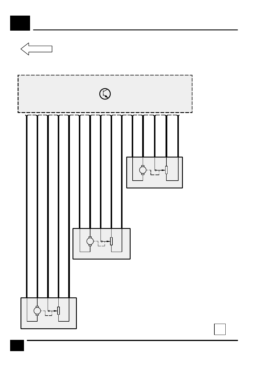
HEATING AND VENTILATION (WITHOUT A/C)

K3

6

CIRCUIT DIAGRAM

C1597

Z253
Heating
Ventilation and
Air Conditioning
Control Unit
(HEVAC)

4

S

2

RB

15

W

16

N

6

B

1

S

5

RB

7

W

9

N

10

B

14

S

13

RB

8

W

11

N

12

B

M

M

M

M165
Distribution
Motor

M164
Right Blend
Motor

M163
Left Blend Motor

HEATING AND VENTILATION (WITH A/C)

K4

CIRCUIT OPERATION

1

CIRCUIT OPERATION

Ignition position 1 (Accessories)

This feed is obtained from the BeCM via fuse 8 and
is shared with the Radio, Front cigar lighter and car
phone (if fitted). The Ignition 1 is essential to the
control panel as it provides power to the ECU
although no functions or display on the LCD are
possible.

Ignition position 2

This feed is obtained from the BeCM via fuse 35.

Battery feed

This feed is obtained from the fuse box via fuse 42.

Ground Connection

This feed runs down to a spliced joint, joining the
main earth run down to fascia earth point E0562.

Dimmer Line

This Pulse Width Modulated signal is provided by the
BeCM.

LCD Dimmer line

This line is a input to the HEVAC and the signal is a
inverse Pulse Width Modulated signal which is
determined by the instrument pack.

Compressor Clutch

The clutch line provides a 12 volt power feed to the
compressor clutch via pressure switch 1.

Condenser Fans

The HEVAC panel provides a signal normally at 12
volts for “off” condition and 0 volts for the “on”
condition, which in the case of petrol vehicles is fed
into the ECM and diesel vehicles directly onto the
coil of relay 18. In line is the Air–Conditioning
pressure switch 2, which turns the fans on/off.

When relay 18 is energised, it provides connection
between relays 13 and 14 (fan 1 and 2) in series or
parallel with each other. This is dependent upon the
state of the air–conditioning pressure switch 1.

For the petrol option, when the signal enters the
ECM, the ECM will switch the output on/off to the
fusebox. The ECM will switch the output on
sometimes for engine cooling reasons even though
the engine has been turned off.

Aspirator

There are two parts of this sensor, one of which is a
fan which draws cabin air onto the temperature
sensor. The temperature sensor then sends the
signal back to the HEVAC ECU.

Ambient Sensor

This sensor measures the temperature of the
external air flow into the vehicle.

The ambient temperature sensor is located behind the
LH side of the vehicle in front of the condenser. The
revised location improves the response time of the
sensor. The new HEVAC software will not update the
ambient temperature sensor readings unless the
vehicle is travelling over approximately 15 mph (25
km/h). The HEVAC software will therefore not auto-
matically correct temperature readings when a faulty
ambient temperature sensor is renewed.

Temperature

Resistance (Ohms)

–20

°

 C (–4

°

 F)

94.5 K

–10

°

 C (14

°

 F)

54.3 K

    0

°

 C (32

°

 F)

32.1 K

  10

°

 C (50

°

 F)

19.7 K

  20

°

 C (68

°

 F)

12.5 K

  30

°

 C (86

°

 F)

  8.1 K

  40

°

 C (104

°

 F)

  5.4 K

Heater Core Sensor

This sensor measures the engine coolant
temperature within the fascia area.

Evaporator Sensor

This sensor is located within the evaporator unit and,
by providing feedback to the HEVAC ECU, prevents
it from freezing.

Alternator Charge signal

This signal is given to the HEVAC ECU to inform it
that the engine is running. This signal is active low.

Diagnostic K line

This line is used to communicate with the diagnostic
equipment (TESTBOOK) and is normally held at 12V
when not active.

Road Speed

This signal is fed into the HEVAC ECU.

Solar Sensor

This sensor provides the HEVAC ECU with the
power of the sun’s solar load and allows the system
to compensate accordingly.

A/C Request

This signal is active low and sends a request to the
ECM to switch on the air–conditioning system.

HEATING AND VENTILATION (WITH A/C)

K4

CIRCUIT OPERATION

2

A/C Grant

This signal is active low and sends a signal to the
HEVAC ECU to acknowledge the request signal and
that it is ready for the load to be switched on by the
HEVAC system.

Pressure switch 1 (Trinary switch)

This switch is in parallel with two components, the
condensor fans and the compressor clutch which are
both normally short circuit. If the pressure is too high
or too low, the switch will open and cut the feed to
the clutch to prevent damage to the system. With the
third setting, at a specific pressure the switch is
shorted and changes the condenser fan mode from
series to parallel.

Pressure switch 2 (Single switch)

The switch is normally open circuit. At a specific
pressure, the switch is shorted and allows the
condenser fans to turn on.

Left/Right Recirculation motors

These motors control the flaps on the blower motor
modules. The flaps should be in one of two
positions, either fully open or fully closed.

Left/Right Blower modules

The blowers have a permanent 12V feed to them.
The speed of the motors is determined by the control
lines which go to the motors. The motors also
provide a voltage feedback to the HEVAC ECU to
determine the actual voltage at the motors but also
to show if there are any faults.

Left/Right Blend and Distribution Motors

These motors are controlled by the HEVAC ECU
which provides power to the motors, which in turn
report back their actual positions to the HEVAC
ECU.

HEATING AND VENTILATION (WITH A/C)

K4

3

CIRCUIT DIAGRAM

REV: 11/99

Data Link
Connector

25

C0448

NY

C0162

25

C0448

C0203

15

C1289

Petrol

Diesel

Z106
Generator

S573

Starting and
Charging

D +

6

30

F 8

30 A

Z238
Body Electrical
Control Module
(BECM)

RL7

C1276

S212

WK

Z253
Heating
Ventilation and
Air Conditioning
Control Unit
(HEVAC)

1

4

C0792

S208

E0562

6

7

C0793

LGR

KR

15

C0040

7

S213

S214

X318
Data Link Connector (OBDII)

B

See Ground
Distribution

P125a
Engine
Compartment
Fuse Box

30

F 42

10 A

8

C0574

15

F 35

10 A

3

C0575

3

2

S211

See Fuse Details

C0226D

C0185

C0792

Petrol
Diesel

Radio

See Fuse
Details

Power
Distribution

NY

S137

W

Navigation
System


Content   ..  201  202  203  204   ..