Range Rover 2. Electrical Manual - part 171
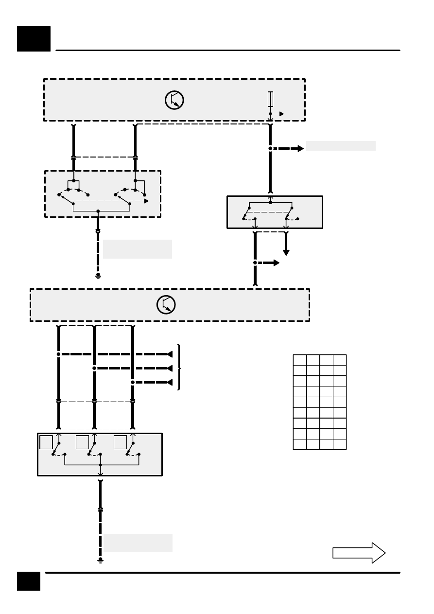
IGNITION AND SHIFT INTERLOCK
C1
2
CIRCUIT DIAGRAM
REV: 08/99
P
0
1
1
R
0
0
1
N
1
0
1
D
1
0
0
3
0
0
0
2
0
1
0
1
1
1
0
Z*
1
1
1
X
Y
Z
Z238
Body Electrical
Control Module
(BECM)
Z238
Body Electrical
Control Module
(BECM)
9
C1276
W
15
1
C0075
[1]
X168
Stop Lamp
Switch
[1]
Brake Pedal
Depressed
0
[1]
0
S211
See Fuse Details
13
C1280
WK
X134
Ignition Switch
8
W
0
I
II
III
0
I
II
III
3
2
C0028
See Ground
Distribution
E0562
4
C0028
3
GP
4
C1276
S201
2
C0075
YP
Anti–Lock Brake
System
F 17
10 A
1 =
0 =
* =
Switch Open
Switch Closed
Fault
8
UB
1
X294
Gear Box
Position Switch
[1]
X Switch
[2]
Y Switch
[3]
Z Switch
[1]
0
9
UP
2
See Ground
Distribution
6
BS
E0808
C0244
[2]
0
5
C0745
4
3
18
C1287
UG
3
[3]
0
C0244
5
C0988
S608
S609
S610
Automatic
Gearbox
C0988
C0745
X
Y
Z