Range Rover 2. Electrical Manual - part 42
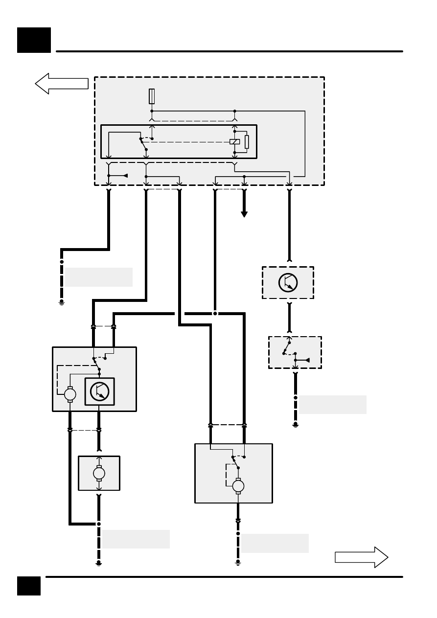
WASH/WIPE
F5
4
CIRCUIT DIAGRAM
15
F 38
10 A
RL11
[11]
2
3
1
5
5
C176
4
5
4
1
2
C172
P125a
Engine Compart-
ment Fuse Box
[11] Headlamps
Wash/Wipe
Relay
LGR
NU
LGU
LGU
B
S101
E154
See Ground Dis-
tribution
S111
E181
See Ground Dis-
tribution
4
W
6
C113
M
1
C191
2
C191
M
[1]
[2]
4
C160
1
C160
M
[1]
[2]
3
C190
2
R
B
4
B
B
2
1
C190
S114
E167
See Ground Dis-
tribution
Z238
Body Electrical
Control Module
(BECM)
M110
Headlamp Wash
Pump
C175
C177
M157
Right Headlamp
Wiper Motor
[1]
Run
[2]
Park
M156
Left Headlamp
Wiper Motor
[1]
Run
[2]
Park
3
C257
U
4
C219
3
C219
B
X145
Main Lighting
Switch
[2]
Headlamps
E252
See Ground Dis-
tribution
S208
[2]
0
S132
Security/Central
Locking
YB
RB
B
YB
RB