Range Rover 2. Electrical Manual - part 13
DIESEL
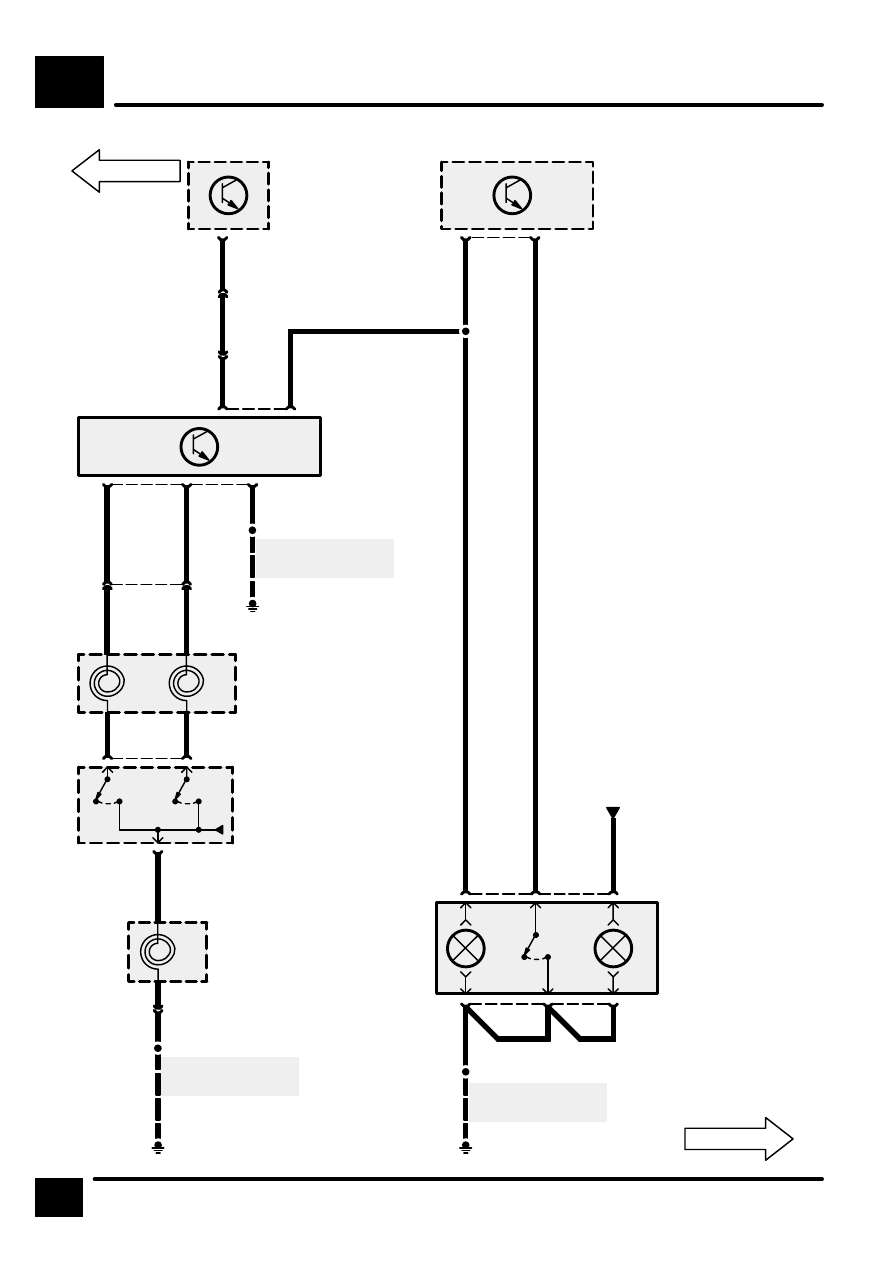
A6
14
CIRCUIT DIAGRAM
REV: 07/98
E252
S215
0
[6]
0
[7]
6
C247
PB
Z119
Rotary Coupler
X269
Steering Wheel
Switches
[6]
Reset/Decel
[7]
Set/Accel
B
See Ground
Distribution
3
C247
2
W
R
Z119
Rotary Coupler
5
C235
W
R
2
C235
1
5
C241D
6
E252
S207
B
See Ground
Distribution
YR
YS
4
C241D
8
C572
20
YO
2
C102
C202
OY
OY
19
C571
C121
Z249
Cruise Control
Converter/In-
verter Module
Z132
Engine Control
Module (ECM)
C255
14
WY
Z238
Body Electrical
Control Module
(BECM)
18
OW
E252
S208
X115
Cruise Control
Switch
B
See Ground
Distribution
4
C211
B
3
6
C211
1
2
B
5
S202
Interior Lamps
RW
0
1
2