Range Rover BORG WARNER 44-62 TRANSFER BOX. Manual - part 3
TRANSFER BOX
8
DESCRIPTION AND OPERATION
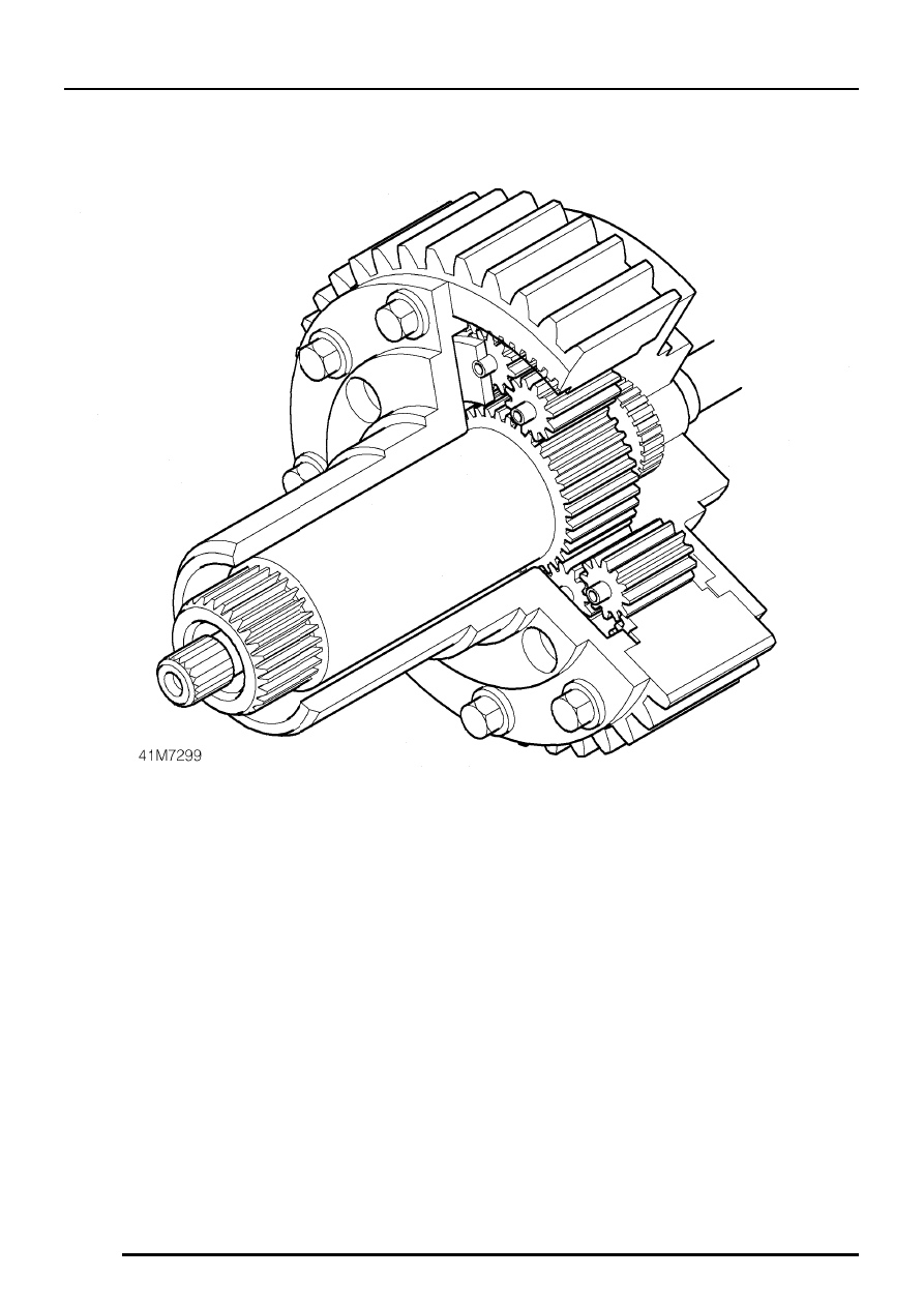
Differential unit
The differential unit is driven from the intermediate
shaft through a Morse chain. The outer casing of the
differential unit is the differential input, while the sun
gear provides the front output and the planet carrier
the rear output.
The planet carrier contains three sets of gears,
which mesh in pairs to maintain the correct
directional relationship between front and rear
differential outputs. The rear output shaft passes
through the differential unit, engaging with the planet
carrier and protruding through the sun gear shaft to
locate to the VCU inner spline. The sun gear shaft
locates to the VCU outer spline.