Range Rover Body Repair Manual - part 20


  Index      Land Rover     Range Rover - Body Repair Manual 1996 year


Search            


Content   ..  18  19  20  21   ..


Range Rover Body Repair Manual - part 20


CHASSIS AND BODY

5

REPAIR

CENTRE CONSOLE

Service repair no - 76.25.01

Remove

1. Remove electric window switch pack.

See

ELECTRICAL, Repair.

2. Disconnect rear footwell lamp multiplug.
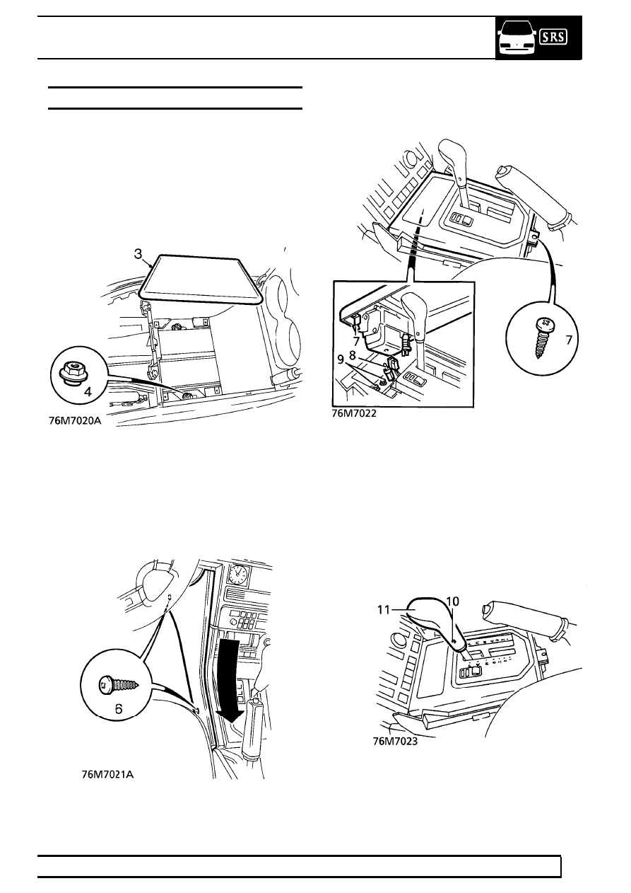
3. Remove base in console bin.

4. Remove nuts securing rear of console to floor

studs.

5. Move both front seats fully rearward.
6. Remove 2 screws securing each side panel to

centre console. Release sprag clips from fascia
switch pack by firmly pulling rearwards. Remove
side panels.

7. Remove screw at rear of gear lever applique.

Raise rear end of applique to disengage 2 spring
clips at forward end.

8. Disconnect cigar lighter multiplug, release cigar

lighter bulb. Remove gear lever applique.

9. Manual gearbox models:

Remove gear knob. Remove 2 bolts securing
front of console to floor.

10. Automatic gearbox models:

Remove 2 screws securing selector lever.

11. Remove selector lever.

76

CHASSIS AND BODY

NEW RANGE ROVER

6

REPAIR

12. Remove 3 screws securing selector graphics

plate.

13. Raise selector graphics plate, disconnect

multiplug.

14. Remove selector graphics plate.
15. All models:

Remove clip securing park brake lever clevis pin,
remove clevis pin. Raise park brake lever to
vertical position.

16. Raise rear of console to disengage rear vent

ducts. Remove centre console.

Refit

17. Fit centre console, ensuring that ducts to rear

fresh air vents are correctly engaged.

18. Fit nuts securing centre console to floor.
19. Automatic - position graphics plate over selector

lever, connect multiplug.

20. Align graphics plate to console, secure with

screws.

21. Fit selector lever, secure with screws.
22. Manual - secure front of centre console to floor

with bolts.

23. Fit gear knob.
24. Lower park brake lever, fit clevis pin and secure

pin with clip.

25. Position gear/selector lever applique, connect

cigar lighter multiplug and insert illumination bulb
in holder.

26. Engage applique clips to console. Secure

applique with screw.

27. Position console side panels. Firmly push

forward to engage sprag clips into fascia switch
pack. Fit and tighten screws.

28. Return front seats to original positions.
29. Fit base to console bin, tighten with screws.
30. Connect rear footwell lamp multiplug.
31. Fit electric window switch pack.

See

ELECTRICAL, Repair.

CHASSIS AND BODY

7

REPAIR

CHASSIS CROSS MEMBER

Remove

1. Disconnect battery negative lead.
2. Raise vehicle on four post lift.
3. Support transmission with a suitable stand.
4. Remove and discard 6 nuts securing

transmission mount to crossmember. Remove
snubber bar.

5. Remove 3 of 4 nuts and bolts securing each side

of crossmember to chassis.

6. With assistance, remove remaining bolt securing

crossmember. Remove crossmember.

Refit

7. With assistance, position crossmember to

chassis. Secure with nuts and bolts. Tighten to
45 Nm. (33 lbf.ft)

8. Fit snubber bar. Secure transmission mount to

crossmember with new flange nuts. Tighten to
45 Nm. (33 lbf.ft)

9. Remove support from transmission.

10. Lower vehicle.
11. Reconnect battery negative lead.

76

CHASSIS AND BODY

NEW RANGE ROVER

8

REPAIR

ENGINE ACOUSTIC COVER

Service repair no - 76.11.06

Remove

1. Raise front of vehicle.

WARNING: Support on safety stands.

2. Release 4 threaded fasteners securing engine

acoustic cover to chassis brackets.

3. Release acoustic cover from brackets and

manoeuvre past steering gear.

Refit

4. Fit acoustic cover to brackets and secure with

threaded fasteners.

GEARBOX LOWER ACOUSTIC COVER

Service repair no - 76.11.13

Remove

1. Raise front of vehicle.

WARNING: Support on safety stands.

2. Release 6 threaded fasteners securing lower

acoustic cover to side acoustic covers.

3. Remove lower acoustic cover.

Refit

4. Fit acoustic cover to side acoustic covers.
5. Tighten threaded fasteners securing lower cover

to side covers.

6. Remove stand(s) and lower vehicle.


Content   ..  18  19  20  21   ..