Range Rover. Manual - part 300


  Index      Land Rover     Range Rover P38 - service manual 1995 year


Search            


Content   ..  298  299  300  301   ..


Range Rover. Manual - part 300


WIPERS AND WASHERS

1

DESCRIPTION AND OPERATION

WIPER AND WASHER SYSTEM

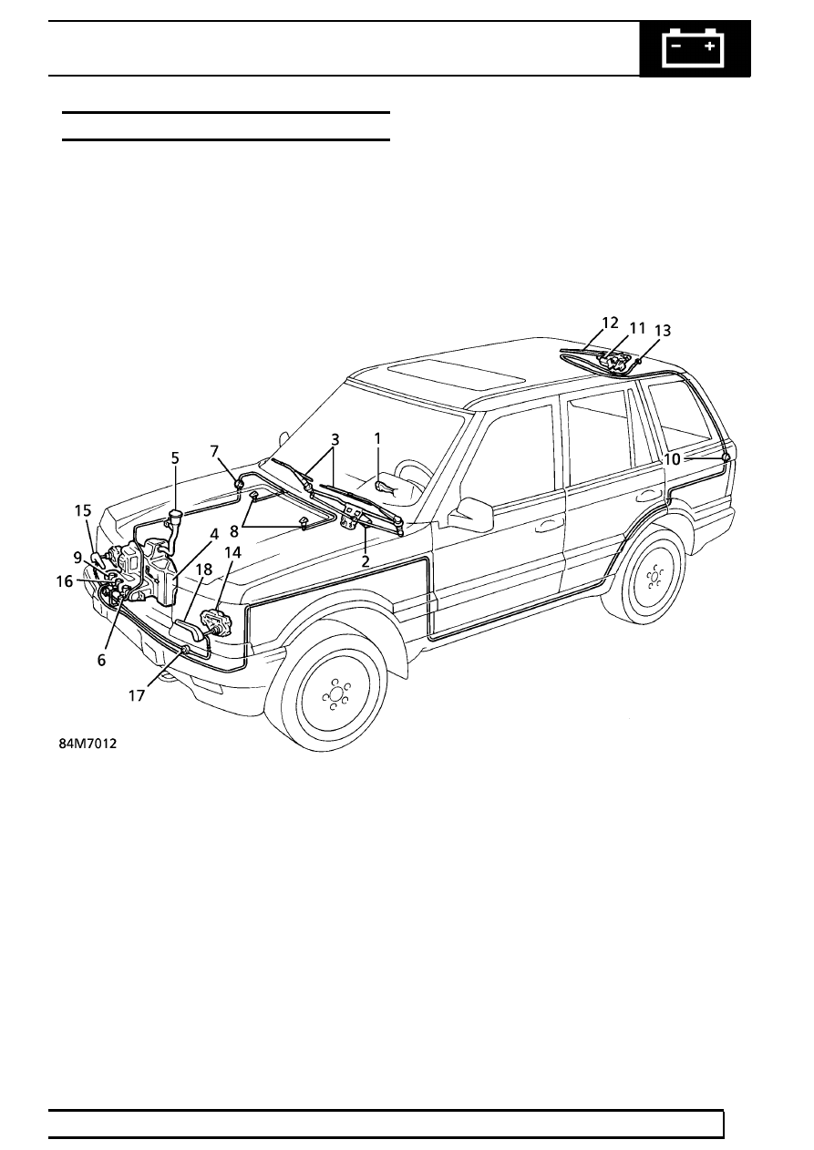
The illustration below locates and identifies the main
components in the wiper and washer system, which is
operated by a multi-switch (1) on the RH side of the
steering column. All functions of the system are
described in the following pages.

1. Multi-switch
2. Wiper motor, windscreen
3. Wiper arm/blade
4. Washer reservoir
5. Filler cap tube, washer reservoir
6. Windscreen washer pump
7. Non return valve
8. Washer jets
9. Rear screen washer pump

10. Non return valve

11. Wiper motor, rear screen
12. Wiper arm/blade
13. Washer jet
14. Wiper motor, headlamp
15. Wiper arm/blade
16. Washer pump, headlamp
17. Non return valve
18. Washer jet
19. Low screen wash sensor

84

WIPERS AND WASHERS

NEW RANGE ROVER

2

DESCRIPTION AND OPERATION

Description

A chassis mounted washer reservoir (4), with low
screen wash sensor (19) and extended filler cap tube
(5), is fitted and supplies both front and rear washers
using integral pump motors (6) and (9). When
headlamp wash/wipe is installed a separate pump
(16) is used in the system, including a non return
valve (17) for each side.

Two bonnet mounted windscreen washer jets (8),
using a single non return valve (7) are linked to the
system by rubber tubing and plastic connectors.
Reinforced plastic tubing, supplying the front and rear
screen washers, is taped in with the electrical harness
routed along the inside wings of the engine
compartment to facilitate production. A similar
arrangement is used to route the rear washer tubing
from the vehicle ’A’ post to the non return valve (10).

The windscreen wiper motor (2) is located in the
plenum chamber on the driver’s side and uses a
conventional linkage arrangement to operate the
wiper arms and blades (3). The rear wiper motor (11)
is secured to the screen frame and drives a single
wiper arm/blade (12) that parks horizontally behind a
finisher panel, which also hides the washer jet (13).
When fitted, the headlamp wiper motor (14) is
installed in the lower rear of the headlamp unit and
drives a wiper arm/blade assembly, which includes
twin washer jets (18), see 84M7013.

WIPERS AND WASHERS

3

DESCRIPTION AND OPERATION

WINDSCREEN WIPER AND WASHER OPERATION

The windscreen wipers and washers can only function
with the starter switch turned to positions 1 or 2.

Raise or lower the multi-switch lever to operate the
windscreen wipers only, from position O for each
function, see 84M7013.

Single wipe

Raise the lever to position 1.
The wipers will continue to wipe for as long as the
lever is held in this position.

Intermittent wipe

Lower the lever to position 2.
To vary the delay between wipes rotate the thumb
wheel to the right to increase the delay; to the left to
decrease the delay.

Continuous wipe, slow speed

Lower the lever to position 3.

Continuous wipe, fast speed

Lower the lever to position 4.

NOTE: Functions 1 to 4 will also operate
when the lever is pulled rearwards.
However, in this position the rear screen

intermittent wipe will also function.

Windscreen wash/wipe

Press and hold the lower button (5) at the end of the
lever, see 84M7014.
The washers and wipers will operate for as long as
the button is pressed. When the button is released the
washers stop, but the wipers will continue for a further
three full wipes before parking.

A momentary press of the button will initiate a
programmed wash/wipe cycle.After a short period the
washers will stop and the wipers continue for a further
three full wipes before parking. Moving the lever to
any other front wipe position during the programmed
wash/wipe will cancel the remainder of the
programmed cycle.

If the fluid level in the washer reservoir is low, the
programmed wash/wipe will only operate for as long
as the button is pressed; there will be no timed wash
or additional three wipes.

84

WIPERS AND WASHERS

NEW RANGE ROVER

4

DESCRIPTION AND OPERATION

REAR SCREEN WIPER AND WASHER
OPERATION

Intermittent wipe

Pull the multi-switch lever back to engage rear screen
intermittent wipe, see 84M7015.
All functions of the windscreen wipers are also
available in this position.

If the front wipers are operating in intermittent mode
the rear wiper will function on every second operation
of the front wipers.

Rear screen wash/wipe

Press and hold the upper button (6) at the end of the
lever, see 84M7016. The washer and wiper will
operate for as long as the button is pressed. When the
button is released the washer will stop, but the wiper
will continue for a further three wipes before parking.

A momentary press of the button will initiate a
programmed wash/wipe cycle. After a short period,
the washer will stop and the wiper will complete a
further three wipes before parking. Moving the lever to
any other rear wipe position during the programmed
wash/wipe will cancel the remainder of the
programmed cycle.

If the fluid level in the washer reservoir is low, the
programmed wash/wipe will only operate for as long
as the button is pressed; there will be no timed wash
or additional three wipes.

The rear wash/wipe will not operate if the tailgate is
open.

The rear wiper will operate automatically when
reverse gear is selected, if the windscreen wipers are
functioning in any mode.

HEADLIGHT WASH/WIPE

Headlight wash/wipe is controlled via a timer unit
which is activated by the windscreen washer system,
only when the headlamps are switched on.

Headlight wash/wipe functions on the first operation of
the windscreen wash/wipe and thereafter at every
other wash/wipe.

If the fluid level in the washer reservoir is low the
headlight wash/wipe will not function at all.

WASHER RESERVOIR LOW SCREEN WASH
LEVEL

The message centre will display ’LOW SCREEN
WASH LEVEL’ whenever the front or rear wash/wipe
systems are used and the screen wash level is low.
The message is also activated whenever the starter
switch is turned to, or from position 2.


Content   ..  298  299  300  301   ..