Range Rover. Manual - part 262
PANEL REPAIRS
1
PROCEDURES
GENERAL WELDING PRECAUTIONS
For ease of reference the diagrams on the following
pages show only the type of weld used in repair where
this varies from that used in production.
When carrying out welding operations the following
criteria must be observed:
•
Where resistance spot welds have been
used in production, these must be
reproduced with new spot welds in
replacement where possible. All such
reproduction spot welds must be spaced
30mm (1.2in.) apart.
•
When spot welding, it is recommended that
test coupons of the same metal gauges
and materials are produced to carry out
peel tests to ensure that welding
equipment being used can produce a
satisfactory joint. Plug welds must be used
if a satisfactory spot weld cannot be
produced.
•
The electrode arms on hand-held spot
welding guns must not exceed 300mm
(11.81in.)in length.
•
Single-sided spot welding is not
acceptable.
•
Brazing and gas welding are not
acceptable EXCEPT where they have been
specified in production.
•
Where 3 metal thicknesses or more are to
be welded together it is imperative to use
MIG plug welds to ensure joint strength.
•
MIG plug welds must be used in repair
joints where there is no access for a
resistance spot welder. To replace each
production spot weld an 8 mm (0.31 in)
hole must be drilled and/or punched, and a
MIG weld then made in its place. The
number of plug welds must match exactly
the number of spot welds which have been
removed.
•
Where holes are left in an existing panel
after removal of the spot welds, a single
MIG plug weld will be made in each hole as
appropriate.
•
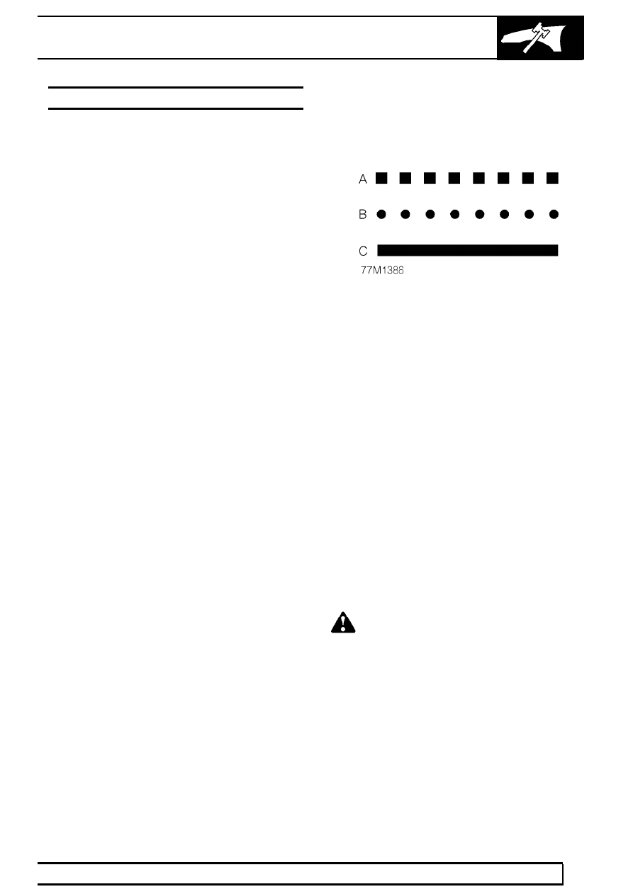
The replacement welds in the welding
diagrams are denoted by the following
symbols:
A. Single thickness plug welds
B. Multiple thickness plug welds
C. MIG seam weld
Seat Belt Anchorages
Seat belt anchorages are safety critical. When making
repairs in these areas it is essential to follow design
specifications. Note that High Strength Low Alloy
(HSLA) steel may be used for seat belt anchorages.
Where possible, the original production assembly
should be used, complete with its seat belt
anchorages, or the cut line should be so arranged that
the original seatbelt anchorage is not disturbed.
All welds within 250mm (9.9in.) of seat belt
anchorages must be carefully checked for weld
quality, including spacing of spot welds.
WARNING: Body parts incorporating seat
belt anchorages MUST be renewed
completely if damaged beyond repair, as
the welds in these areas are safety critical and
cannot be disturbed.