Range Rover. Manual - part 229


  Index      Land Rover     Range Rover P38 - service manual 1995 year


Search            


Content   ..  227  228  229  230   ..


Range Rover. Manual - part 229


CHASSIS AND BODY

11

REPAIR

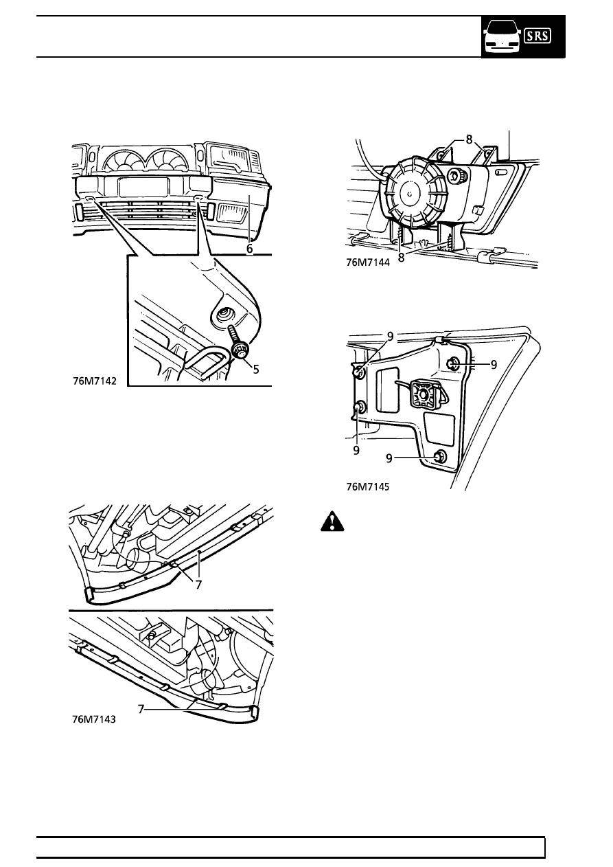
5. Remove 2 bumper bolt access plugs from

bumper valance. Remove bolts.

6. With assistance remove bumper assembly.

Do not carry out further dismantling if
component is removed for access only.

7. Remove 8 studs and 6 clips securing extensions

spoiler. Remove extension.

8. Remove 8 screws securing fog lamps. Remove

lamps.

9. Remove 8 bolts securing bumper end brackets

to bumper. Remove brackets.

WARNING: If front bumper is damaged due
to impact, the impact cans must be
inspected. There must be no visible

deformation. The overall length must be 188.25
mm æ 0.5 mm. Replace the impact cans if
necessary.

Refit

10. Fit end brackets and secure with bolts. Fit fog

lamps and secure with screws.

11. Fit extension and secure with clips and studs.
12. With assistance fit bumper assembly, tighten

bolts to

70Nm. (52 lbf.ft)

13. Fit bolt access plugs.
14. Align end brackets, tighten bolts and secure

bumper end clips.

15. Connect fog lamp multiplugs and breather

hoses, fit battery cover.

16. Remove safety stands. Lower vehicle.

76

CHASSIS AND BODY

NEW RANGE ROVER

12

REPAIR

EXTENSION SPOILER FRONT BUMPER

Service repair no - 76.22.78

Remove

1. Raise the vehicle.

WARNING: Support on safety stands.

2. Remove 8 studs and 6 clips securing spoiler to

front bumper.

3. Remove spoiler halves.

Refit

4. Fit spoiler halves to bumper. Secure with clips

and studs.

5. Remove safety stands. Lower vehicle.

REAR BUMPER VALANCE

Service repair no - 76.22.74

Remove

1. Raise the vehicle.

WARNING: Support on safety stands.

2. Remove rear road wheels.
3. Remove 3 screws securing each mud flap.

Remove mud flaps.

4. Remove 2 screws securing each wheel arch

liner extension panel to rear bumper/chassis.

5. Remove 2 wheel arch liner extension panels.
6. Release 2 clips securing bumper ends to

mounting brackets.

CHASSIS AND BODY

13

REPAIR

7. Disconnect 3 towing harness multiplugs.
8. Remove 2 mounting bolt covers.
9. Remove 2 bolts securing bumper to chassis.

10. With assistance, release bumper ends from

brackets. Remove bumper.

Refit

11. With assistance, position bumper. Engage nylon

end supports to brackets.

12. If necessary, slacken bolts securing end support

brackets. Align bumper to body. Tighten to
29 Nm. (22 lbf.ft)

13. Fit bumper mounting bolts. Tighten to

70 Nm.

(52 lbf.ft)

14. Fit bolt covers.
15. Secure bumper end clips.
16. Connect towing harness multiplugs.
17. Position wheel arch liner extensions. Secure with

screws.

18. Position mud flaps. Secure with screws.
19. Fit road wheels. Tighten to

108 Nm. (80 lbf.ft)

20. Remove safety stands. Lower vehicle.

FASCIA ASSEMBLY

Service repair no - 76.46.23/99

WARNING: The fascia assembly houses
the heater distribution unit, blower
assemblies and air conditioning

evaporator. Assistance is essential during
removal and refit procedures.

CAUTION: When removed from the
vehicle, the fascia should be placed on a
soft covered work surface, supported on

suitable wooden blocks.

Remove

1. Vehicles with SRS only: Remove battery.

See

ELECTRICAL, Repair.

2. Vehicles without SRS: Disconnect battery

negative lead.

3. Drain cooling system.

See COOLING SYSTEM,

Repair.

4. Loosen hose clips, disconnect hoses from

heater pipes.

5. Remove centre console.

See this section.

6. Remove steering column.

See STEERING,

Repair.

7. Remove wiper motor and linkage.

See WIPERS

AND WASHERS, Repair.

8. Disconnect passenger side heated front screen

multiplug. Release multiplug from clip.

76

CHASSIS AND BODY

NEW RANGE ROVER

14

REPAIR

9. Remove 6 bolts, remove remaining scuttle side

panel.

10. Remove heater intake pollen filters.
11. Remove 8 screws securing each pollen filter

housing. Remove both housings.

12. Remove radio.

See ELECTRICAL, Repair.

13. Release door aperture seal adjacent to ’A’ post

lower trim panels.

14. Driver’s side - LHD automatic vehicles only:

Remove 3 bolts securing foot rest through ’A’
post lower trim, remove foot rest.

15. Remove screw securing each ’A’ post lower trim

panel, release from single sprag clip, remove
both trim panels.


Content   ..  227  228  229  230   ..