Range Rover. Manual - part 195


  Index      Land Rover     Range Rover P38 - service manual 1995 year


Search            


Content   ..  193  194  195  196   ..


Range Rover. Manual - part 195


ELECTRONIC AIR SUSPENSION

5

REPAIR

Refit

8. Clean splines and seal mating faces.
9. Lubricate lip of oil seal, fit to axle case.

10. Apply a 3mm band of Loctite (grade 648) to hub

flange spline.

11. Fit hub to half shaft and fit nut, finger tight.
12. Remove shaft and hub assembly from vice.
13. Fit hub to axle case, fit bolts. Tighten to

65 Nm.

(48 lbf.ft)

14. Clean ABS sensor, bush and mating face.
15. Fit a new ABS sensor bush. Fit sensor to

location in hub.

16. Fit brake disc shield.

See BRAKES, Repair.

17. Remove safety stands. Lower vehicle.
18. Tighten drive shaft nut to

260 Nm. (192 lbf.ft)

19. Stake the nut.
20. Fit road wheel centre.

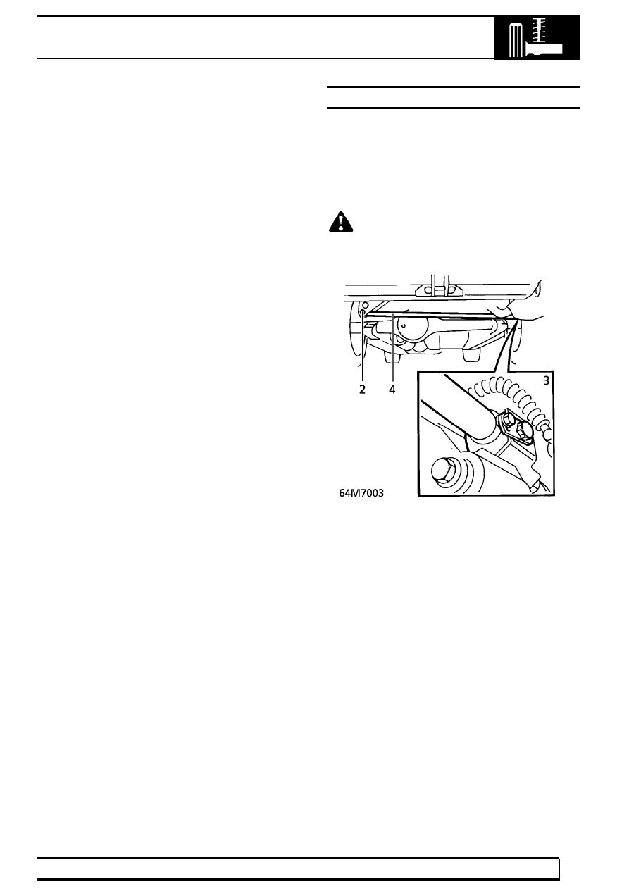
PANHARD ROD AND BUSHES

Service repair no - 64.35.50 - Panhard rod
Service repair no - 64.35.51 - Bushes

Remove

1. Raise the vehicle.

WARNING: Support on safety stands.

2. Remove nut and bolt securing panhard rod to

chassis.

3. Remove locking plate screw, locking plate and

bolt securing panhard rod to axle.

4. Remove panhard rod.
5. Press out bushes from panhard rod. Ensure that

pressure is applied to the outer edge of bush,
not rubber inner.

64

REAR SUSPENSION

NEW RANGE ROVER

6

REPAIR

Refit

6. Clean mating faces of bushes in rod.
7. Press in new bushes.

CAUTION: Ensure that pressure is applied
to the outer edge of bush, not rubber
inner.

8. Fit panhard rod. Tighten nut and bolt to

200 Nm.

(148 lbf.ft)

9. Tighten bolt to

200 Nm. (148 lbf.ft)

10. Fit locking plate and screw. Tighten screw to

20 Nm. (15 lbf.ft)

11. Remove safety stands. Lower vehicle.

SHOCK ABSORBER

Service repair no - 64.30.02

Remove

WARNING: Unrestricted movement of
pressurised air spring will result in failure
of the assembly, causing component

damage and possible personal injury. It is
possible to remove the shock absorber without
depressurising air springs, BUT the distance
between axle and chassis must be held as if
damper assembly is fitted. This is achieved by
supporting vehicle on safety stands with a jack
under the axle.

1. Raise the vehicle.

WARNING: Support on safety stands.

2. Support axle on jack.
3. Remove road wheel.

WARNING: Do not lower axle when shock
absorber is removed. This may result air
spring failure.

ELECTRONIC AIR SUSPENSION

7

REPAIR

4. Remove bolt securing shock absorber to

chassis.

5. Remove shock absorber lower fixing.
6. Remove shock absorber.

Refit

7. Fit shock absorber, ensure lower mounting

rubbers are fitted as shown.

8. Tighten top mounting bolt to

125 Nm. (92 lbf.ft)

9. Tighten lower mounting nut to

45 Nm. (33 lbf.ft)

10. Fit road wheel. Tighten to

108 Nm. (80 lbf.ft)

11. Remove jack.
12. Remove safety stands. Lower vehicle.

TRAILING ARM AND BUSHES

Service repair no - 64.35.46 - Trailing arm
Service repair no - 64.35.48 - Bushes

Remove

1. Raise vehicle on four post lift.
2. Depressurise air suspension.

See FRONT

SUSPENSION, Repair.

3. Raise rear of vehicle to give enough clearance

for shock absorber to be disconnected.

4. Remove nut securing shock absorber to axle.

Release shock absorber, collect mounting
rubbers.

5. Release height sensor link from trailing arm.

CAUTION: Ensure that rubber mounting
does not become damaged.

6. Remove 2 nuts and bolts securing trailing arm to

axle.

7. Remove nut and bolt securing trailing arm to

chassis.

8. Remove trailing arm.

64

REAR SUSPENSION

NEW RANGE ROVER

8

REPAIR

Do not carry out further dismantling if component
is removed for access only.

9. Using LRT-64-001, press bush from trailing arm.

10. Using LRT-64-001, press new bush into trailing

arm.

CAUTION: LRT-64-001 must be used to
compress the bush as it is pressed into
the arm. Damage to bush will result if

correct tool is not used.

Refit

11. Position trailing arm to vehicle and align to

chassis. Fit bolt but do not tighten at this stage.

12. Secure trailing arm to axle with nuts and bolts.

M16 with 8.8 strength grade - Tighten to
160 Nm. (118 lbf.ft),
M16 with 10.9 strength grade - Tighten to
240 Nm. (177 lbf.ft),
M12 - Tighten to

125 Nm. (92 lbf.ft)

13. Engage height sensor link into trailing arm

location.

14. Position upper mounting rubber. Engage shock

absorber to axle.

15. Position lower mounting rubber and washer.

Secure shock absorber to axle with nut. Tighten
to

45 Nm. (33 lbf.ft)

CAUTION: Washer must be fitted with
convex side towards rubber.

16. Remove safety stands. Lower vehicle.
17. Tighten bolt securing trailing arm to chassis.

Tighten to

160 Nm. (118 lbf.ft)

18. Lower ramp.


Content   ..  193  194  195  196   ..