Range Rover. Manual - part 194


  Index      Land Rover     Range Rover P38 - service manual 1995 year


Search            


Content   ..  192  193  194  195   ..


Range Rover. Manual - part 194


ELECTRONIC AIR SUSPENSION

1

REPAIR

CHASSIS FIXINGS

CAUTION: Ensure all under body wax is
removed from mating surfaces of fixings
before fitting.

AIR SPRING - REAR

Service repair no - 64.21.01

Remove

WARNING: Air suspension is pressurised
up to 10 bar (150 psi). Dirt or grease must
not enter the system. Wear hand, eye and

ear standard protection when servicing system.

WARNING: The air spring must be
restricted by suspension loading, with
dampers fitted before inflation. Failure to

observe this warning could result in air spring
damage, resulting in component failure or
personal injury. DO NOT ATTEMPT TO
DISMANTLE AIR SPRING.

1. Remove wheel arch liner.

See CHASSIS AND

BODY, Repair.

2. Support chassis under rear cross member.

Depressurise suspension.

See FRONT

SUSPENSION, Repair.

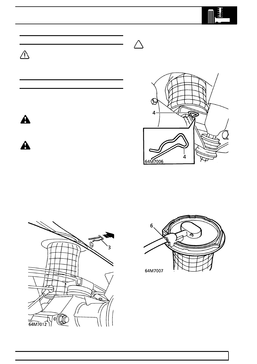
3. Using a suitable hooked tool, remove clip

securing air spring to chassis.

NOTE: Access to clip is under wheel arch
between body and chassis.

4. Remove clip securing air spring to axle.

5. Raise chassis for clearance to remove spring.

Resupport chassis.

6. Release air spring from chassis and axle for

access to air pipe connection, clean connection
and disconnect pipe.

7. Seal pipe and air spring. Remove spring.

64

REAR SUSPENSION

NEW RANGE ROVER

2

REPAIR

CAUTION: When refitting the air spring,
DO NOT allow the vehicle to rest on the
deflated air spring.

The chassis must be supported until the air spring
is inflated.

Refit

8. Clean mating faces of axle, chassis and air

spring.

9. Fit air spring, remove seal from spring and air

pipe. Connect pipe to spring.

10. Align spring to chassis, with assistance fit

securing clip.

CAUTION: Ensure air hose is correctly
routed.

11. Remove support from chassis, lower spring onto

axle and refit support.

12. Fit clip to secure spring to axle.
13. Carry out leak test.

See FRONT SUSPENSION,

Repair.

BUMP STOP

Service repair no - 64.30.15

Remove

1. Raise the vehicle.

WARNING: Support on safety stands.

2. Remove bump stop from body.

Refit

3. Fit bump stop.
4. Remove safety stands. Lower vehicle.

ELECTRONIC AIR SUSPENSION

3

REPAIR

HEIGHT SENSOR - REAR

Service repair no - 64.36.01

Remove

1. Raise the vehicle.

WARNING: Support on safety stands.

2. Release height sensor multiplug from bracket on

body. Disconnect multiplug from body harness.

3. Disconnect height sensor link from trailing link.

CAUTION: Ensure that rubber mounting
does not become damaged.

4. Remove 2 bolts securing height sensor to

chassis.

5. Remove height sensor.

Refit

6. Fit height sensor to chassis, fit bolts. Tighten to

12 Nm. (9 lbf.ft)

7. Connect height sensor link to trailing link.
8. Connect height sensor multiplug to body

harness. Secure multiplug to bracket on body.
Ensure that cable is correctly routed around
brackets.

9. Remove safety stands. Lower vehicle.

10. Recalibrate system if a new sensor has been

fitted.

See FRONT SUSPENSION, Repair.

HEIGHT SENSOR - REAR - 97 MY ON

Service repair no - 64.36.01

Remove

WARNING: Ensure air suspension is made
safe before commencing work. Chassis
may otherwise lower onto axle bump stops

during repair.

1. Raise rear of chassis and position LRT-60-003

between bump stop and axle.

2. Lower chassis onto LRT-60-003.
3. Raise rear of vehicle.

WARNING: Support on safety stands.

4. Disconnect multiplug from height sensor.
5. Disconnect height sensor lever arm from trailing

arm.

6. Remove 2 nuts securing height sensor to

chassis.

7. Remove height sensor.

Refit

8. Position height sensor to chassis.
9. Fit nuts and tighten to

6 Nm. (4 lbf.ft)

10. Connect height sensor lever arm to trailing arm.
11. Connect multiplug to height sensor.
12. Remove stand(s) and lower vehicle.
13. Raise chassis and remove LRT-60-003.
14. Lower chassis.
15. Recalibrate system using TestBook if a new

sensor has been fitted.

64

REAR SUSPENSION

NEW RANGE ROVER

4

REPAIR

DRIVE SHAFT AND HUB ASSEMBLY

Service repair no - 64.15.01

Remove

NOTE: This procedure gives removal
instructions for the drive shaft and oil seal,
plus the hub, bearing and drive flange

assembly.

NOTE: If the hub and drive shaft are to be
removed as an assembly, it is not
necessary to slacken the drive shaft nut.

1. Remove centre cap from front wheel, release

stake from drive shaft nut. Slacken nut.

2. Remove brake disc shield.

See BRAKES,

Repair.

3. Remove 2 bolts, remove backplate strap from

hub.

4. Release ABS sensor from hub, remove sensor

seal and bush.

5. Remove 6 bolts, remove hub and half shaft

assembly from axle.

6. Secure hub and half shaft assembly in vice.

Remove drive shaft nut and remove hub from
shaft.

7. Remove seal from axle casing.


Content   ..  192  193  194  195   ..