Range Rover. Manual - part 188


  Index      Land Rover     Range Rover P38 - service manual 1995 year


Search            


Content   ..  186  187  188  189   ..


Range Rover. Manual - part 188


ELECTRONIC AIR SUSPENSION

13

REPAIR

HEIGHT SENSOR - 97 MY ON

Service repair no - 60.36.01

Remove

WARNING: Ensure air suspension is made
safe before commencing work. Chassis
may otherwise lower onto axle bump stops

during repair.

1. Raise front of chassis and position LRT-60-003

between bump stop and axle.

2. Lower chassis onto LRT-60-003.
3. Raise front of vehicle.

WARNING: Support on safety stands.

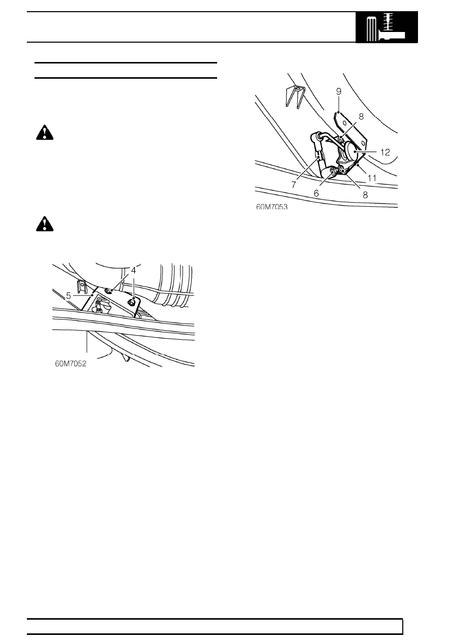
4. Remove 2 bolts securing heat shield to height

sensor.

5. Remove heat shield.

6. Remove nut securing height sensor lever arm to

radius arm.

7. Release sensor lever arm from radius arm.
8. Remove 2 bolts securing height sensor to

chassis.

9. Collect heat shield mounting bracket and 2

washers.

10. Position height sensor cover to gain access to

height sensor multiplug.

11. Disconnect multiplug and remove height sensor

assembly.

12. Remove cover from height sensor.

Refit

13. Fit cover to height sensor.
14. Fit bolts and washers to height sensor assembly.
15. Position height sensor to chassis and connect

multiplug.

16. Position heat shield bracket, fit height sensor

assembly and tighten bolts to

6 Nm. (4 lbf.ft) .

17. Engage sensor lever arm to radius arm, fit nut

and tighten to

8 Nm (6 lbf.ft) .

18. Position heat shield to bracket, fit bolts and

tighten to

6 Nm (4 lbf.ft) .

19. Remove stand(s) and lower vehicle.
20. Raise chassis and remove LRT-60-003.
21. Lower chassis.
22. Recalibrate system using TestBook if a new

sensor has been fitted.

60

FRONT SUSPENSION

NEW RANGE ROVER

14

REPAIR

DRIVE SHAFT AND HUB ASSEMBLY

Service repair no - 60.25.01

Remove

NOTE: This procedure gives removal
instructions for the drive shaft and oil seal,
plus the hub, bearing and drive flange

assembly.

1. Remove centre cap from front wheel, release

stake from drive shaft nut. Slacken nut.

NOTE: If the hub and drive shaft are to be
removed as an assembly, it is not
necessary to slacken the drive shaft nut.

2. Raise the vehicle.

WARNING: Support on safety stands.

3. Remove brake disc shield.

See BRAKES,

Repair.

4. Release ABS sensor harness from brackets on

hub and axle.

5. Release sensor from hub.
6. Remove sensor bush.

7. Remove 4 bolts securing hub to carrier.

ELECTRONIC AIR SUSPENSION

15

REPAIR

8. Release hub from carrier. Remove hub and drive

shaft assembly.

9. Remove drive shaft nut. Remove shaft assembly

from hub.

10. Remove drive shaft seal from axle casing.

Refit

11. Clean ABS sensor and location. Clean drive

shaft and its seal location. Clean hub bearing
carrier and its location in hub.

12. Lubricate oil seal lip and its running surface on

drive shaft.

13. Fit oil seal to axle case, using service tool

LRT-51-012.

14. Apply a 3mm band of Loctite (grade 648) to hub

flange spline.

15. Fit drive shaft to hub. Fit stake nut, do not

tighten.

16. Fit hub and drive shaft assembly. Fit bolts.

Tighten to

135 Nm (100lbf.ft)

17. Lightly grease ABS sensor and bush, using the

correct silicone grease.

See LUBRICANTS,

FLUIDS AND CAPACITIES, Information.

18. Fit ABS sensor bush.
19. Fit ABS sensor fully into bush, secure lead to

brackets.

20. Fit brake disc shield.

See BRAKES, Repair.

21. Tighten drive shaft nut to

260 Nm. (192 lbf.ft)

22. Stake the nut.
23. Fit road wheel centre.
24. Remove safety stands. Lower vehicle.

60

FRONT SUSPENSION

NEW RANGE ROVER

16

REPAIR

ANTI-ROLL BAR LINK

Service repair no - 60.10.02

Remove

1. Raise the vehicle.

WARNING: Support on safety stands.

2. Remove nuts securing link to chassis and

anti-roll bar.

3. Remove link.

Refit

4. Fit link to anti-roll bar and chassis.
5. Fit securing nuts. Tighten to

125 Nm. (92 lbf.ft)

6. Remove safety stands. Lower vehicle.

PANHARD ROD AND BUSHES

Service repair no - 60.10.10. Panhard rod
Service repair no - 60.10.07. Bushes

Remove

1. Raise the vehicle.

WARNING: Support on safety stands.

2. Remove nut and bolt securing panhard rod to

chassis.

3. Remove locking plate screw, locking plate and

bolt securing panhard rod to axle.

4. Remove panhard rod.
5. Press out bushes from rod.


Content   ..  186  187  188  189   ..