Range Rover. Manual - part 150


  Index      Land Rover     Range Rover P38 - service manual 1995 year


Search            


Content   ..  148  149  150  151   ..


Range Rover. Manual - part 150


ZF AUTO

1

DESCRIPTION AND OPERATION

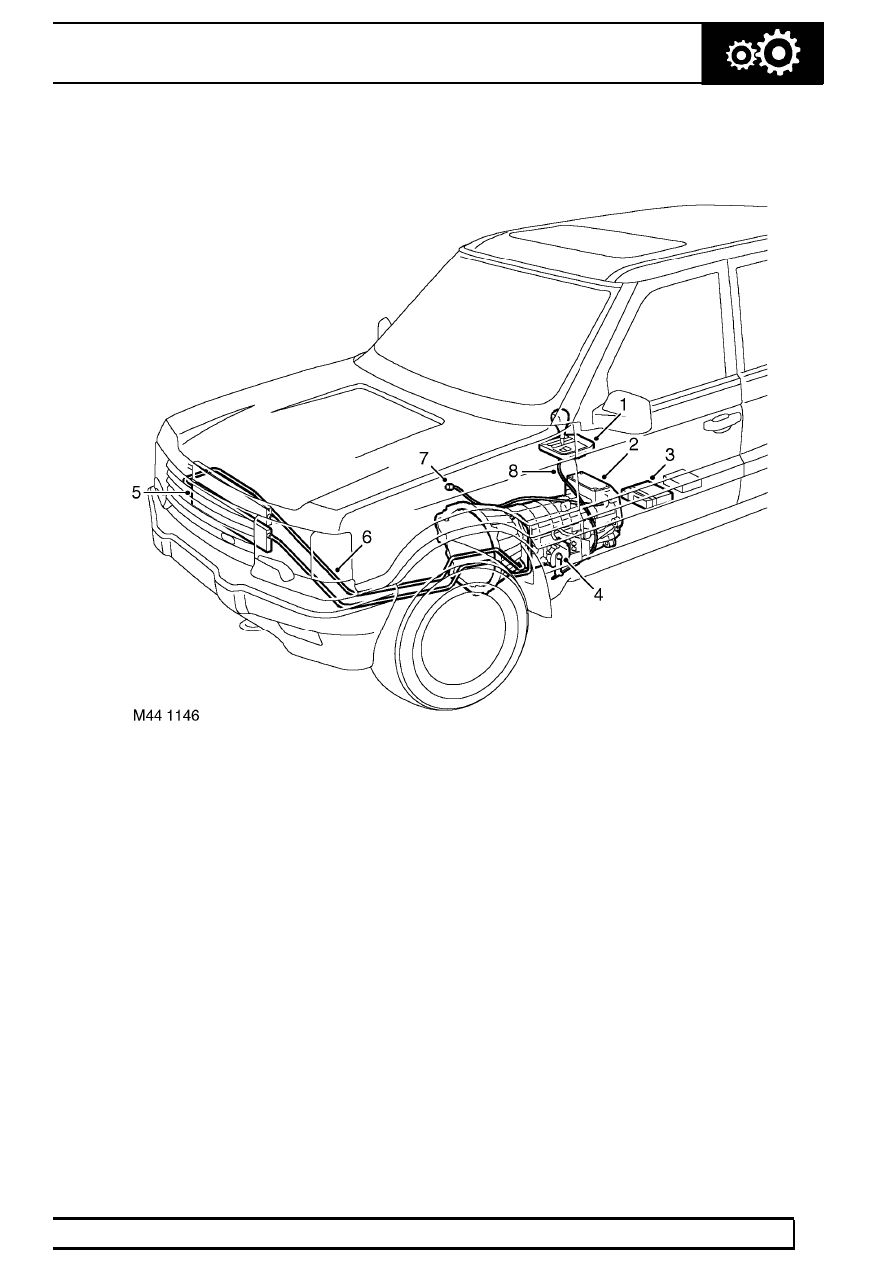
Electronic Automatic Transmission component layout

1. Selector lever assembly
2. Gearbox
3. Electronic Automatic Transmission (EAT) ECU
4. Selector position switch

5. Oil cooler
6. Fluid lines
7. Breather tube
8. Selector cable

44

AUTOMATIC GEARBOX

NEW RANGE ROVER

2

DESCRIPTION AND OPERATION

Electronic Automatic Transmission control schematic

ZF AUTO

3

DESCRIPTION AND OPERATION

1. Transmission high/low switch
2. Mode switch
3. Gear position switch connector
4. Solenoid valve/speed sensor connector
5. Electronic Automatic Transmission (EAT) ECU
6. Engine Control Module (ECM)

7. Diagnostic socket
8. Instrument pack
9. Transmission fluid temperature sensor

10. Body electrical Control Module (BeCM)
11. Battery power supply
12. Ignition power supply

44

AUTOMATIC GEARBOX

NEW RANGE ROVER

4

DESCRIPTION AND OPERATION

AUTOMATIC TRANSMISSION - DESCRIPTION

General

The ZF4HP22 transmission is used on 2.5 litre Diesel
and 4.0 litre petrol models. 4.6 litre petrol models use
the ZF4HP24 transmission unit to accomodate the
increased power output of the larger engine. Both
units are of similar construction with the ZF4HP24 unit
being slightly longer. The operation of both units is the
same.

Automatic transmission vehicles are fitted with an
’H-gate’ selector mechanism. The selector mechanism
combines the operation of the transmission selector
lever and the transfer box high/low gear range
selection. Selections on the selector lever assembly
are transmitted by a selector cable to a gear position
switch.

The gear position switch on the transmission passes
gear selection signals to an Electronic Automatic
Transmission (EAT) ECU located below the LH front
seat, which outputs the appropriate control signals to
an electro-hydraulic valve block in the transmission. A
mode switch enables the driver to change the control
mode of the EAT ECU between manual, economy and
sport. The EAT ECU provides signals to the message
centre in the instrument pack to indicate the control
mode and system status.

The gearbox features a pressure lubrication system
and is cooled by pumping the lubricant through an oil
cooler located in front of the engine cooling radiator.

From 99MY onwards, petrol models feature a revised
EAT ECU with Controller Area Network (CAN) digital
communications between the EAT ECU and the ECM.

H-gate selector lever assembly

The selector lever assembly consists of a lever and a
cover attached to a cast base. The base is located on
a gasket and secured to the transmission tunnel and
has an ’H’ pattern for the lever to move in. The lever is
hinged to the base and a latch in the lever engages
with detents in the base to provide positive location for
the lever positions. The latch is disengaged by
pressing a release button on the lever knob as shown
in the lever illustration below.


Content   ..  148  149  150  151   ..