Range Rover. Manual - part 65


  Index      Land Rover     Range Rover P38 - service manual 1995 year


Search            


Content   ..  63  64  65  66   ..


Range Rover. Manual - part 65


EMISSION CONTROL

21

DESCRIPTION AND OPERATION

Identification

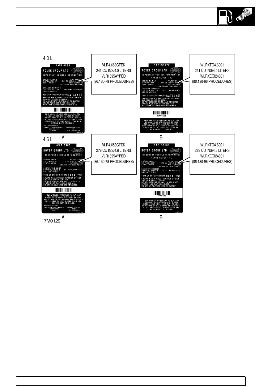
The system was introduced on all North American
specification vehicles from 1998 Model Year.
Advanced EVAP vehicles can be recognised by the
information contained in the EVAP. FAMILY entry on
the underbonnet Emission label (mounted on the
bonnet lock platform).

A - Vehicles without advanced EVAPS
VLR1095AYPBD

B - Vehicles with advanced EVAPS
WLRXEO124001

17

EMISSION CONTROL

NEW RANGE ROVER

22

DESCRIPTION AND OPERATION

Evaporative emission control system - Advanced
EVAPS.

The evaporation emission control system is used to
reduce the level of hydrocarbons emitted into the
atmosphere from the fuel system. The system
comprises a vapour separator (B) and an anti-trickle
valve (A), both located on the fuel filler neck (F), an
Evaporative Emissions (EVAP) canister and an EVAP
canister purge valve. A Canister vent solenoid (CVS)
unit is mounted in front of the EVAP canister on
vehicles up to 99MY. On vehicles from 99MY the CVS
unit is mounted near the bulkhead on the RHS of the
engine bay. The CVS unit is used by the ECM to
control fresh air supply to the canister.

On NAS vehicles, the fuel pump and gauge sender
unit incorporates a pressure sensor which is used by
the ECM, in conjunction with the CVS unit, to
determine the presence of leaks which may cause
vapour to escape. This system is added for
compliance with OBD measures.

A

Anti-trickle fill valve

B

Liquid/Vapour Separator

C

Vent line to pressure sensor

D

From fuel tank to liquid/vapour separator

E

From EVAP canister to anti-trickle fill valve

F

Fuel filler neck assembly

G

Internal fill breather hose

During conditions of high ambient temperatures, fuel
in the tank vapourises, and pressure rises. Fuel
vapour enters the vapour separator and any liquid fuel
runs back to the tank. Two roll over valves are fitted in
the fuel tank vapour lines. These valves prevent liquid
fuel entering the vapour separator if the vehicle rolls
over. The advanced EVAPS system has no two way
valve, so vapour is free to flow to the EVAP canister,
where it is stored in the canister’s activated charcoal
element. When the correct engine operating
conditions are met, the Engine Control Module (ECM)
opens the EVAP canister purge valve and vapour is
drawn from the canister, into the plenum chamber to
be burned in the engine. Fresh air is drawn into the
canister through the EVAP canister vent solenoid to
take up the volume of displaced vapour. During
normal operating conditions, and when the engine is
switched off, the vent solenoid remains open and the
fuel tank is free to breath through the EVAP canister.
If the vent solenoid should fail, or the main vapour line
becomes blocked, excess pressure is vented to
atmosphere through a valve in the fuel filler cap.
Similarly, the cap vent valve will open to prevent the
tank collapsing if excessive vacuum is present.

When the temperature of fuel in the tank reduces,
pressure also reduces and vapour must be drawn
back into the tank. Fresh air is drawn into the canister,
through the open vent solenoid, to take up the
displaced volume.

EMISSION CONTROL

23

DESCRIPTION AND OPERATION

An anti-trickle fill valve is fitted to the filler neck in the
line between the tank and EVAP canister. The
function of this valve is to prevent the user overfilling
the tank by trickling fuel into the neck, thereby
preserving the vapour space in the tank to allow for
fuel expansion during hot weather.

The valve creates a blockage in the vent line during
the fuel filling process. The valve is operated by the
action of inserting the fuel filler gun. With the valve in
the closed position, air displaced during filling exits the
tank only through the internal fill breather. When the
fuel level reaches the level of the fill breather, the filler
neck fills with fuel, shutting off the filler gun.

The breather ports from the EVAP canister are
located high up in the engine bay (CVS unit on NAS
vehicles, snorkel tubes on ROW vehicles), to prevent
water ingress during vehicle wading.

The advanced evaporative loss control system used
on NAS vehicles is similar to the standard system, but
also includes a CVS unit and an in-tank pressure
sensor to monitor the pressure build-up for
determining whether leaks are present.

The function of the CVS unit is to block the
atmospheric vent side of the EVAP canister to enable
the ECM to carry out the EVAP system leak check.
The leak check is only carried out when the vehicle is
stationary and the engine is running at idle speed. The
test uses the natural rate of fuel evaporation and
engine manifold depression. Failure of the leak check
will result in illumination of the Malfunction Indicator
Lamp (MIL).

The fuel evaporation leak detection is included as part
of the On-Board Diagnostics (OBD) strategy and
checks for leaks greater than 1mm (0.04 in.) in
diameter. During checking, the vent and purge lines
are closed for a reference check on system pressure
to be determined. Then the purge valve is opened,
exposing the fuel tank and vent lines to engine
vacuum. The ECM then checks the signal from the
fuel tank pressure sensor for any pressure increase
(i.e loss of vacuum) which would indicate a leakage.

Any fuel evaporation system leaks which occur
between the output of the purge valve and the
connection to the inlet manifold cannot be determined
using this test, but this type of fault will be detected
through the fuelling adaption diagnostics.

EXHAUST EMISSION CONTROL COMPONENTS -
(from 99MY)

Catalytic converters

The catalytic converters are located in each of the
front pipes from the exhaust manifolds. The catalytic
converter’s housings are fabricated from stainless
steel and are fully welded at all joints. Each catalytic
converter contains two elements of an extruded
ceramic substrate which is formed into a honeycomb
of small cells with a density of 62 cells / cm

2

. The

ceramic element is coated with a special surface
treatment called ’washcoat’ which increases the
surface area of the catalyst element by approximately
7000 times. A coating is applied to the washcoat
which contains the precious elements Platinum (Pt),
Palladium (PD) and Rhodium(Rh) in the following
relative concentrations: 1 Pt : 21.6 PD : 1 Rh.

The metallic coating of platinum and palladium oxidize
the carbon monoxide and hydrocarbons and convert
them into water (H

2

O) and carbon dioxide (CO

2

). The

coating of rhodium removes the oxygen from nitrogen
oxide (NO

x

) and converts it into nitrogen (N

2

).

NOTE: Catalytic converters for NAS low
emission vehicles (LEVS) from 2000MY
have active constituents of Palladium and

Rhodium only. The proportion of active
constituents are 14 PD: 1 Rh, and the Palladium
coating is used to oxidise the carbon monoxide
and hydrocarbons in the exhaust gas.

CAUTION: Catalytic converters contain
ceramic material which is very fragile.
Avoid heavy impacts on the converter

casing.

CAUTION: Serious damage to the catalytic
converter will occur if leaded fuel or a
lower octane number fuel than

recommended is used. The fuel tank filler neck is
designed to accomodate only unleaded fuel pump
nozzles.

WARNING: To prevent personal injury
from a hot exhaust system, do not attempt
to disconnect any components until the

exhaust system has cooled down.

17

EMISSION CONTROL

NEW RANGE ROVER

24

DESCRIPTION AND OPERATION

Heated oxygen (HO

2

S) sensors

1. Connection cable
2. Disc spring
3. Ceramic support tube
4. Protective sleeve
5. Clamp connection for heating element
6. Heating element
7. Contact element
8. Sensor housing
9. Active sensor ceramic

10. Protective tube
11. Post-catalytic converter sensor (NAS spec. only)
12. Pre-catalytic converter sensor

The heated oxygen sensor is an integral part of the
exhaust emission control system and is used in
conjunction with the catalytic converters and the
engine management control ECM to ensure that the
air:fuel mixture ratio stays around the stoichiometric
ideal, where the catalytic converters are most
effective. Combinations of four (NAS only) or two
heated oxygen sensors are used in the exhaust
system, dependent on market legislation.

The heated oxygen sensors are screwed into
threaded mountings welded into the front exhaust
pipes at suitable locations. They are used to detect
the level of residual oxygen in the exhaust gas to
provide an instantaneous indication of whether
combustion is complete. By positioning sensors in the
stream of exhaust gases from each separate bank of
the exhaust manifold, the engine management system
is better able to control the fuelling requirements on
each bank independently of the other. This facilitates
much closer control of the air:fuel ratio and optimises
catalytic converter efficiency.

CAUTION: HO

2

S sensors are easily

damaged by dropping, excessive heat or
contamination. Care must be taken not to

damage the sensor tip or housing.


Content   ..  63  64  65  66   ..