Range Rover. Manual - part 56


  Index      Land Rover     Range Rover P38 - service manual 1995 year


Search            


Content   ..  54  55  56  57   ..


Range Rover. Manual - part 56


LAND ROVER V8

43

REPAIR

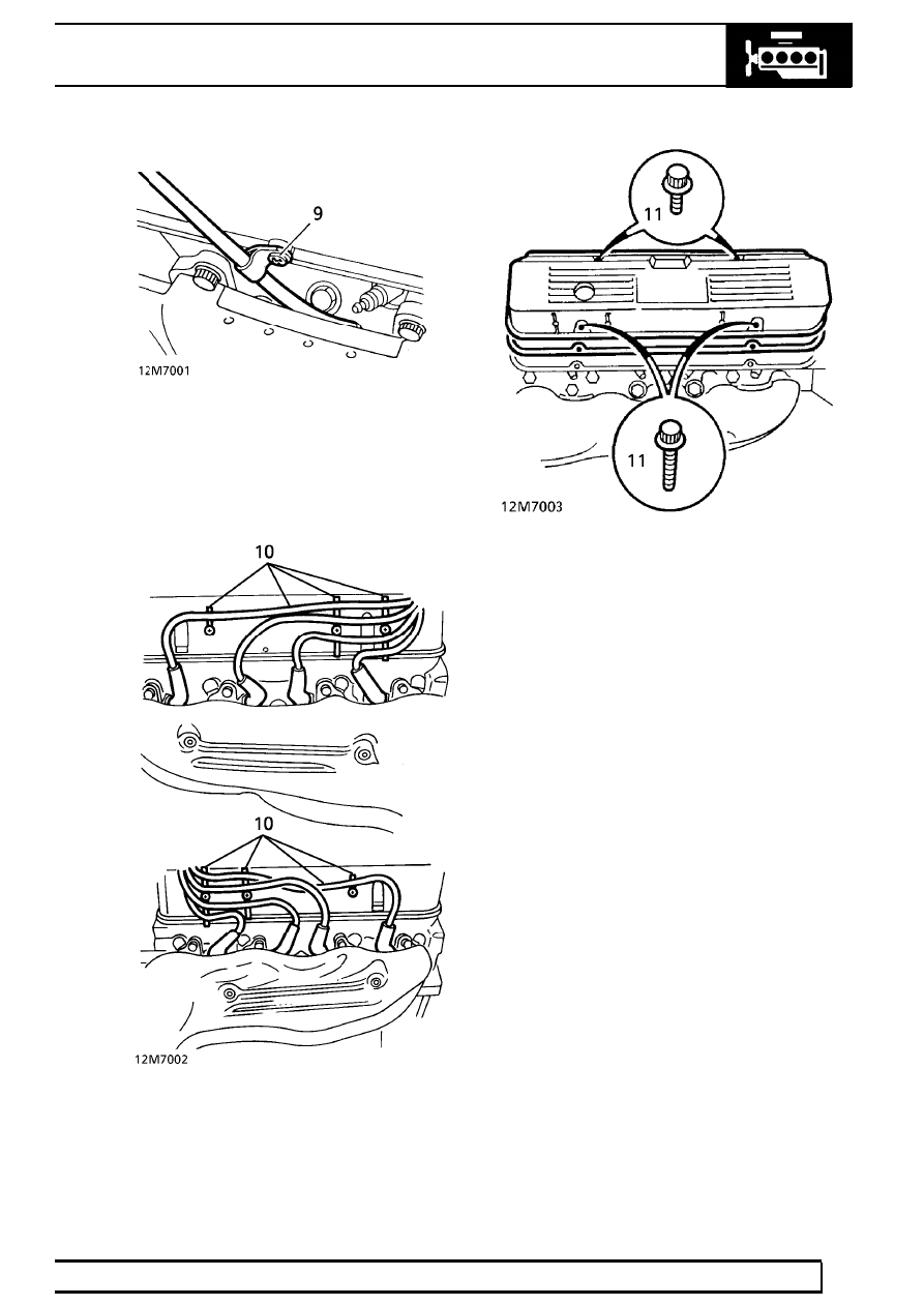
9. Remove screw securing dipstick tube to rocker

cover.

10. Remove H.T. leads from spark plugs and guide

clips on rocker covers.

11. Remove 4 bolts securing rocker cover to cylinder

head.

12. Remove rocker cover.
13. Remove and discard rocker cover gasket.

Refit

14. Clean mating faces between rocker cover and

cylinder head.

15. Refit rocker cover to cylinder head using a new

gasket.

16. Fit rocker cover bolts and tighten by diagonal

selection to :
Stage 1 -

4 Nm (3 lbf.ft)

Stage 2 -

8 Nm (6 lbf.ft)

Stage 3 - Re-torque to

8 Nm (6 lbf.ft)

17. Refit H.T. leads to spark plugs. Secure leads to

rocker cover clips.

18. Align dipstick tube. Secure to rocker cover with

screw.

19. Reconnect purge hose to ram pipe housing.
20. Refit plenum chamber.

See FUEL SYSTEM,

Repair.

21. Secure heater hose to clip on inlet manifold.
22. Secure fuel pressure regulator return pipe in clip.
23. Reconnect fuel feed pipe to fuel rail.
24. Reconnect breather hose to rocker cover.
25. Reconnect battery negative lead.

12

ENGINE

NEW RANGE ROVER

44

REPAIR

ROCKER COVER GASKET (LH) - from 99MY

Service repair no - 12.29.40

Remove

1. Remove upper inlet manifold gasket

See

MANIFOLD AND EXHAUST SYSTEM, Repair.

2. Release HT leads from clips on rocker cover.
3. Remove screw securing dip stick tube.

4. Remove and discard 4 bolts securing rocker

cover.

5. Remove rocker cover and gasket.

Refit

6. Clean mating faces of rocker cover and cylinder

head.

7. Position new gasket on cylinder head.
8. Locate rocker cover on gasket and install

securing bolts.

9. Ensure gasket outer rim is correctly located

around periphery of rocker cover, then tighten
bolts in diagonally opposite sequence to:
Stage 1 -

3 Nm (2.2 lbf.ft).

Stage 2 -

7 Nm (5.2 lbf.ft).

10. Fit and tighten screw securing dip stick tube.
11. Fit plug leads to clips on rocker cover.
12. Fit upper inlet manifold gasket.

See MANIFOLD

AND EXHAUST SYSTEM, Repair.

LAND ROVER V8

45

REPAIR

ROCKER COVER GASKET (RH) - from 99MY

Service repair no - 12.29.41

Remove

1. Drain cooling system.

See COOLING SYSTEM,

Repair.

2. Remove upper inlet manifold gasket.

See

MANIFOLD AND EXHAUST SYSTEM, Repair.

3. Release engine harness clip from coolant rail

and move harness clear of rocker cover.

4. Release clips and disconnect coolant hoses

from heater.

5. Remove 2 bolts securing coolant rails and move

outer rail clear of rocker cover.

6. Remove bolt securing inner coolant rail to inlet

manifold, remove rail and discard ’O’ ring.

7. Release HT leads from clips on rocker cover.

8. Disconnect HT leads from spark plugs and move

clear of rocker cover.

9. Remove and discard 4 bolts securing rocker

cover.

10. Remove rocker cover and gasket.

Refit

11. Clean mating faces of rocker cover and cylinder

head.

12. Position new gasket on cylinder head.
13. Locate rocker cover on gasket and install

securing bolts.

14. Ensure gasket outer rim is correctly located

around periphery of rocker cover, then tighten
bolts in diagonally opposite sequence to:
Stage 1 -

3 Nm (2.2 lbf.ft).

Stage 2 -

7 Nm (5.2 lbf.ft).

15. Connect HT leads to spark plugs and fit leads to

clips on rocker cover.

16. Clean coolant rail ’O’ ring recess.
17. Lubricate and fit new ’O’ ring to coolant rail, fit

rail to inlet manifold and tighten bolt to

22 Nm

(16 lbf.ft).

18. Align outer coolant rail and fit and tighten bolts.
19. Connect coolant hoses to heater and secure

with clips.

20. Reposition engine harness and secure with clip

to coolant rail.

21. Fit upper inlet manifold gasket.

See MANIFOLD

AND EXHAUST SYSTEM, Repair.

22. Refill cooling system.

See COOLING SYSTEM,

Repair.

12

ENGINE

NEW RANGE ROVER

46

REPAIR

ROCKER SHAFT - OVERHAUL

Service repair no - 12.29.49 - LH Shaft
Service repair no - 12.29.50 - RH Shaft
Service repair no - 12.29.55 - Both Shafts

Remove

1. Disconnect battery negative lead.
2. Remove relevant rocker cover.

See this

section.

NOTE: If both shafts are to be removed,
identify each assembly to ensure refitment
on original cylinder bank.

3. Remove 4 bolts securing rocker shaft assembly.

4. Remove rocker shaft assembly. Ensure

pushrods remain seated in tappets.
Do not carry out further dismantling if
component is removed for access only.

5. Remove and discard split pin from one end of

rocker shaft.

6. Remove the following components:

NOTE: Retain components in correct
sequence for re-assembly.

7. Plain washer.
8. Wave washer.
9. Rocker arms.

10. Rocker pillars.
11. Springs.
12. Clean all components.
13. Inspect all components for wear.
14. Inspect rocker shaft and bores in rocker arms. If

excessively worn or scored, fit new components.

15. Replace all weak or broken springs.
16. Lubricate all moving parts with clean engine oil.
17. Re-assemble rocker shafts. Ensure that

components are returned to their original
positions, use new split pins to retain
components.

18. Ensure shaft identification groove is positioned

at one o’clock, with pushrod locations of rocker
arms to the right.

CAUTION: Oil feed restriction will result if
rocker shafts are incorrectly assembled.


Content   ..  54  55  56  57   ..