Range Rover. Manual - part 4


  Index      Land Rover     Range Rover P38 - service manual 1995 year


Search            


Content   ..  1  2  3  4  5  ..


Range Rover. Manual - part 4


INTRODUCTION

13

INFORMATION

LOCATION OF IDENTIFICATION NUMBERS

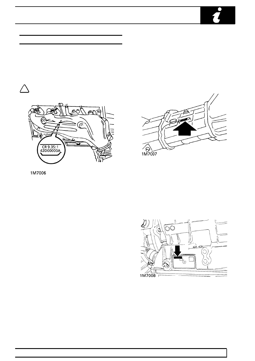
Engine serial number - V8 engine

Stamped on a cast pad on the cylinder block, between
numbers 3 and 5 cylinders.

NOTE: The engine compression ratio is
stamped above the serial number.

Engine serial number - BMW Diesel engine

Stamped on the LH side of the cylinder block above
the sump.

Main gearbox R380 - 5 speed

Stamped on a cast pad on the bottom right hand side
of the gearbox.

Automatic gearbox ZF4HP22/ZF4HP24

Stamped on a plate riveted to the bottom left hand
side of the gearbox casing.

01

INTRODUCTION

NEW RANGE ROVER

14

INFORMATION

Transfer gearbox-Borg Warner

Stamped on a plate attached to the gearbox casing,
between filler/level and drain plug.

Front and rear axle

Stamped on the left hand axle tubes.

Vehicle identification number (VIN)

Made up of 17 digits, these numbers are used to
identify manufacturer, model range, specification,
body type, engine, transmission/steering, model year,
plant and build sequence number and serve to identify
the vehicle.

This example shows the sequence:

European code

S AL LP A M J 7 M A

S Europe

AL UK
LP Range Rover

A European Spec.

M 4 Door Station Wagon

J 4.6 Litre Fuel Injection

7 Manual right steering

M 1995 Model Year

A Solihull

Federal (USA) code

S AL P V 1 2 4 2 S A

S Europe

AL UK

P Range Rover
V North America Spec.

1 4 Door Station Wagon
2 4.0 Litre fuel injection
4 Automatic, Left Hand Steering
2 Check Digit

S 1995 Model Year
A Solihull

INTRODUCTION

15

INFORMATION

EMERGENCY TOWING

CAUTION: The New Range Rover has
permanent four-wheel drive. The following
instructions must be adhered to when

towing:-

Towing the vehicle on four wheels

If it is necessary to recover the vehicle by towing on
all four wheels, ’Transfer neutral’ MUST be selected.

1. With the starter key removed, insert a fuse of 5

amps or more in fuse position ’11’ in the RH seat
fuse box.

2. Turn the starter switch to position ’2’; the transfer

box will now automatically select neutral.

3. Wait until the message centre displays

’TRANSFER NEUTRAL’ and then turn the
starter switch off, position ’0’.

4. Turn the starter switch to position ’1’ to unlock

the steering and leave in this position while the
vehicle is being towed.

5. Secure tow rope to the front towing eye.
6. Release the parking brake.

CAUTION: Power assistance for braking
and steering systems will not be provided
without the engine running. Greater pedal

pressure will be required to apply the brakes, the
steering wheel will require greater effort to turn
the front wheels.
The vehicle tow connection should be used only
in normal road conditions.

CAUTION: DO NOT remove the starter key
or turn the switch to position ’0’ when the
vehicle is in motion.

7. To reactivate the transfer box after towing, turn

the starter switch off to position ’0’ and remove
the fuse from position ’11’. On automatic
vehicles the transfer box will automatically
engage the Low or High gear range.

8. On manual vehicles, first press the range

change switch. The transfer box will then engage
the Low or High gear range.

Suspended tow by breakdown vehicle

CAUTION: To prevent vehicle damage,
front or rear propeller shaft MUST be
removed, dependant upon which axle is

being trailed.

9. To facilitate reassembly, first mark the propeller

shaft drive flanges at transfer box and axle.

10. Remove propeller shaft fixings and lift shaft from

vehicle.

11. If the front axle is to be trailed, turn ignition key

to position ’1’ to release the steering lock.

CAUTION: If the rear axle is to be raised,
the steering wheel and/or linkage MUST be
secured in a straight ahead position. DO

NOT use the steering lock for this purpose.

01

INTRODUCTION

NEW RANGE ROVER

16

INFORMATION

TRANSPORTING THE VEHICLE BY TRAILER

If the vehicle should require transporting on a trailer or
the back of a lorry, the air suspension must be set to
’ACCESS’ before being lashed.

See FRONT

SUSPENSION, Description and operation.

Lashing eyes are provided on the front and rear
chassis cross members to facilitate the securing of the
vehicle, as shown.

CAUTION: DO NOT secure lashing hooks
or trailer fixings to any other part of the
vehicle.

CAUTION: If the air suspension cannot be
set to the ’ACCESS’ position, then the
vehicle must be lashed by its wheels and

not the lashing eyes.

Install vehicle on the trailer and apply park brake.
Select neutral in main gearbox; this will prevent
damage to the parking pawl of the automatic gearbox.


Content   ..  1  2  3  4  5  ..