Frelander 2. Manual - part 645


  Index      Land Rover     Land Rover Frelander 2 - service repair manual 2006-2010 year


Search            


Content   ..  643  644  645  646   ..


Frelander 2. Manual - part 645


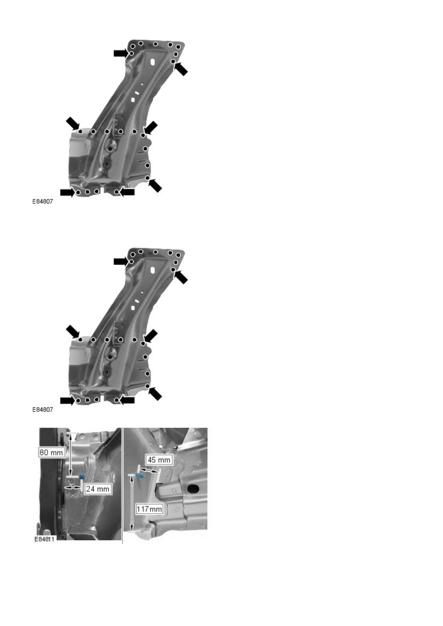
2. Drill holes in the new panel ready for MIG plug welding.

3. Offer up the new panel and clamp into position. Check

alignment, if correct, proceed to next step. If not, rectify and

recheck before proceeding.

4. MIG Plug weld.

5. Install weld studs.

6. Dress all welded joints.
7. The installation of associated panels and mechanical

components is the reverse of removal.

Roof Sheet Metal Repairs - Roof

Description and Operation

Roof service panels

Item

Description

1

Roof  panel

2

Roof rear panel

3

Roof front panel

Time schedules, roof panels

The following times relate to the replacement of the roof panels as single panels. The published times include the removal

of Mechanical, Electrical and Trim, (MET), items, plus paint times based on Metallic Clear Over Base Paint, (blends to

adjacent panels are not included). A corrosion protection time is included where appropriate.

The times were generated by Thatcham, (the Motor Insurance Repair Research Centre), and are to be used as a guide only,

based on new undamaged panels. Job allowances are not included, as a guide Thatcham recommend 0.3 hours to be added

to single panel times.

Single panel times

Panel Description

Times

Roof panel

20.3

Roof rear panel

16.4

Roof front panel

14.4

Roof Sheet Metal Repairs - Roof PanelVehicles Without: Sliding Roof

Opening Panel

Removal and Installation

Removal

• NOTE: The roof is serviced as a separate weld on panel, less its reinforcements.

• NOTE: Along the RH and LH sides of the panel, spot welds should be installed adjacent to the originals and not in the

same locations.

1. The roof panel is replaced in conjunction with:

Liftgate

Windshield

2. For additional information relating to this repair procedure

please see the following:

For additional information, refer to: 

Body and Frame

 (501-26

Body Repairs - Vehicle Specific Information and Tolerance

Checks, Description and Operation) /

Standard Workshop Practices

 (100-00 General Information,

Description and Operation).

3. Disconnect both battery cables.
4. Remove the liftgate.

For additional information, refer to: 

Liftgate

 (501-03 Body

Closures, Removal and Installation).

5. Remove the windshield glass.

For additional information, refer to: 

Windshield Glass

 (501-11

Glass, Frames and Mechanisms, Removal and Installation).

6. Remove both front seats.

For additional information, refer to: 

Front Seat

 (501-10

Seating, Removal and Installation).

7. Remove the rear seat.
8. Remove both side air curtain modules.

For additional information, refer to: 

Side Air Bag Module

(501-20B Supplemental Restraint System, Removal and

Installation).

9. Remove both front safety belt retractors.

For additional information, refer to: 

Front Safety Belt Retractor

(501-20A Safety Belt System, Removal and Installation).

10. Remove both rear safety belt retractors.

For additional information, refer to: 

Rear Safety Belt Retractor

(501-20A Safety Belt System, Removal and Installation).

11. Release and lay aside the wiring harness.

12. Remove 10 21mm headed bolts.

13. Mill out the spot welds.


Content   ..  643  644  645  646   ..