Frelander 2. Manual - part 637
Front End Sheet Metal Repairs - Front Side Member and Suspension Top Mount
Assembly
Removal and Installation
Removal
• NOTE: The front side member and suspension top mount assembly is an assembly of the front side member closing panel, fender
apron panel reinforcement, fender apron panel front extension, fender apron lower panel, front side member and fender apron
panel and the suspension top mount.
• NOTE: The service panel is not fully welded.
• NOTE: The panel is serviced less its weld studs
1. The front side member and suspension top mount assembly is
replaced in conjunction with:
Front bumper cover
Front bumper armature
Hood latch panel
Both front fenders
Front bumper mounting
Fender apron upper panel
Front side member
2. For additional information relating to this repair procedure please
see the following:
For additional information, refer to:
Body and Frame
(501-26 Body
Repairs - Vehicle Specific Information and Tolerance Checks,
Description and Operation) /
Standard Workshop Practices
(100-00 General Information,
Description and Operation).
3. Remove the front side member.
For additional information, refer to:
Front Side Member
(501-27
Front End Sheet Metal Repairs, Removal and Installation).
4. Remove the fender apron upper panel.
For additional information, refer to:
Fender Apron Upper Panel
(501-27 Front End Sheet Metal Repairs, Removal and Installation).
5. Remove the instrument panel.
For additional information, refer to:
Instrument Panel - TD4 2.2L
Diesel
(501-12 Instrument Panel and Console, Removal and
Installation).
6. Remove the rocker panel inner trim.
7. Remove the B-pillar lower trim.
For additional information, refer to:
B-Pillar Lower Trim Panel
(501-05 Interior Trim and Ornamentation, Removal and
Installation).
8. Release and lay aside the front carpet section.
9. Release and lay aside the insulating material at the outer
bulkhead.
10. LH Side: Remove the hood release handle.
11. RH Side: Remove the brake booster.
For additional information, refer to:
Brake Booster
(206-07 Power
Brake Actuation, Removal and Installation).
12. RH Side: Remove the pedal box.
13. Release and lay aside the wiring harnesses at the a-pillar,
bulkhead and side member.
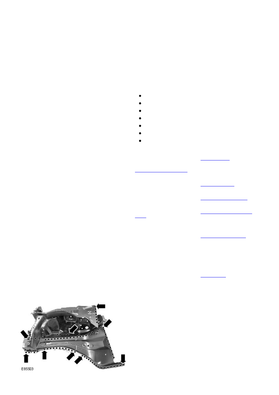
14. Mill out the spot welds.