Frelander 2. Manual - part 627
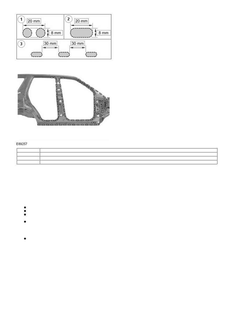
Item
Description
1
Drill 2 x 8mm holes to form basis of slot
2
Mill out to form 20mm x 8mm slot
3
Slots spaced at 30mm intervals
• NOTE: Mig brazing is carried out at a temperature of 650°C to 950°C. To avoid degradation of the ultra high strength
steel material properties, the temperature must be below 950°C.
Mig braze the slot(s) using a Fronius Trans Plus Synergic 2700 4 R/Z/AL MIG Welder, with CuSi3 (DIN 1733) 1.0mm filler
wire with setting parameters 4, which is 92 Amps, Wire feed 4.6 m/min. Shielding gas L1 = pure Argon (DIN 439).
Dress the surface of the weld cap (brazed slot) with 60/80 grit belt sanders.
Accident damage and diagnosis
General notes
Exact diagnosis of the extent of the damage enables proper repair planning.
All body repairs must be carried out in accordance with the guidelines in this Body Repair Manual.
The stability and strength properties of the body must be taken into account during body repairs. The body has
exact defined deformation patterns that must not be affected by any repair work.
For instance, the crumple zones absorb the bulk of the impact energy. If any unprofessional repair techniques or
methods are used in these areas then this can pose a fundamental threat to vehicle safety.
Hidden damage
As well as looking at external indicators like flaked off paint, it is vital to check for hidden body damage or
deformation that is not visible from the outside. Large attached parts like bumpers and inner fenders often need to
be removed to allow accurate assessment of damage to underlying body parts.
Gap dimensions
Gap dimensions offer another alternative for diagnosis by visual inspection. If any changes or misaligned edges are
apparent, then this usually indicates that the dimensions of the affected part are incorrect.
Changes in gap dimension