Frelander 2. Manual - part 620
12
-
Seat position sensor
13
-
Passenger air bag deactivation switch
14
-
Driver safety belt buckle switch
15
-
Passenger safety belt buckle switch
16
-
Impact sensor - left-hand front
17
-
Impact sensor - right-hand front
18
-
Side impact sensor - left-hand B-pillar
19
-
Side impact sensor - right-hand B-pillar
20
-
Side impact sensor - left-hand C-pillar
21
-
Side impact sensor - right-hand C-pillar
22
-
Driver lower air bag
23
-
Adaptive steering column
24
-
Side air bag – left-hand
25
-
Side air bag – right-hand
26
-
Clockspring
27
-
Passenger air bag
28
-
Driver air bag
29
-
Curtain air bag – left-hand
30
-
Curtain air bag – right-hand
PRINCIPLES OF OPERATION
Crash Sensing
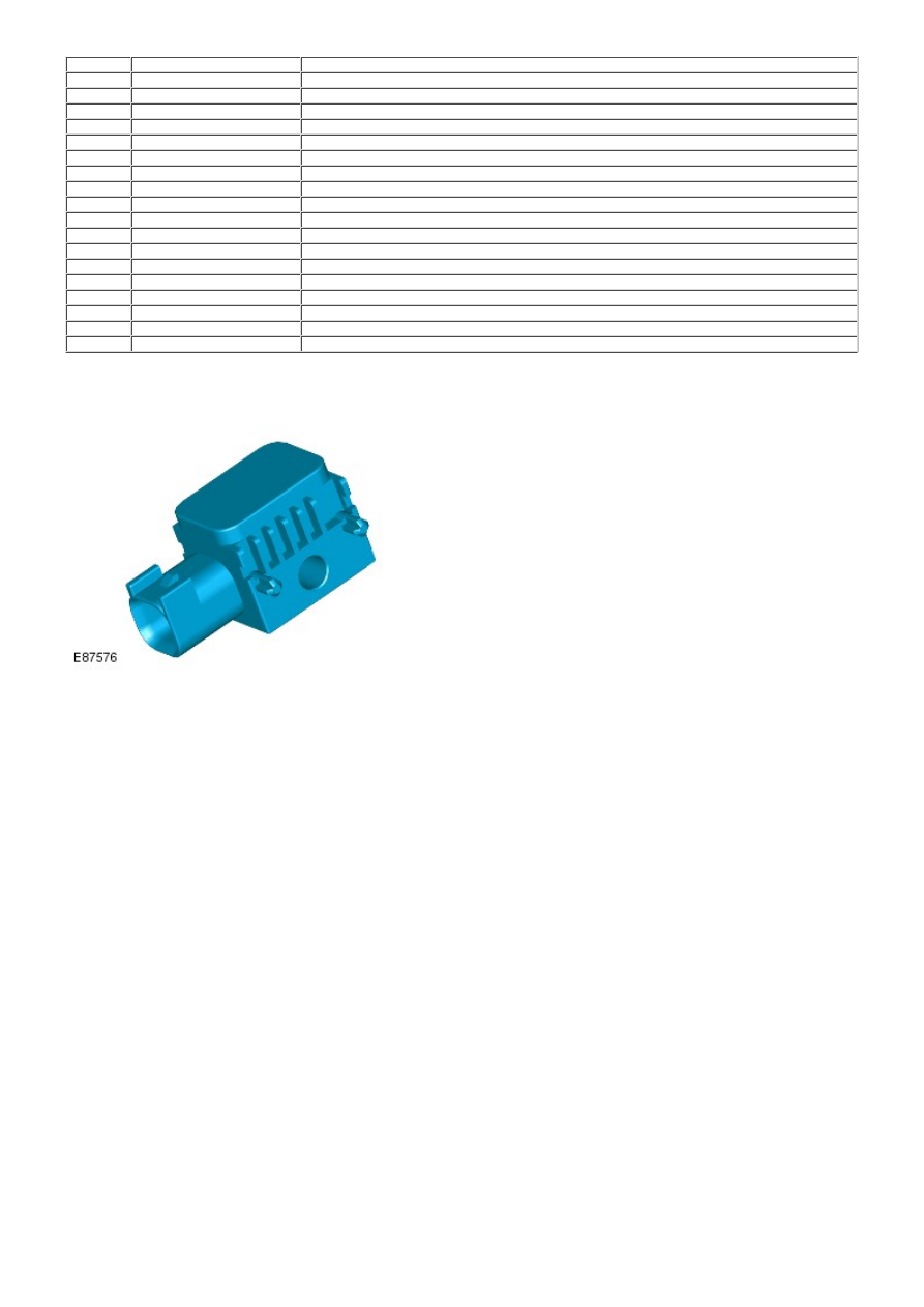
Impact sensor
The impact sensors are installed in the front and both sides of the vehicle. W hen the ignition is switched on the Restraints
Control Module (RCM), supplies power to the impact sensors which perform a self test. After satisfactory self test the
impact sensors continually output 'digital acceleration' messages to the restraints control module. The use of multiple
impact sensors provide shorter air bag trigger times through faster detection of lateral and longitudinal acceleration and
also improves detection accuracy.
Each impact sensor incorporates an accelerometer and a microchip powered by a feed from the restraints control module.
Acceleration is evaluated by the microchip and transmitted to the restraints control module, which then makes the decision
on whether or not to activate the air bags and pretensioners.
If a fault is detected the relevant impact sensor sends a fault message, instead of the digital acceleration message, to
the restraints control module. The RCM then stores a related fault code and illuminates the air bag warning indicator.
Faults can be retrieved by the Land Rover approved diagnostic system from the RCM via the high-speed CAN.
Occupant Monitoring
There are two types of occupant monitoring systems fitted to vehicles:
1. NAS markets, have an Occupant Classification Sensing System.
1.
2. Markets except NAS and Australia, have an Occupant Detection Sensing System.
2.
1. Occupant Classification Sensing System