Frelander 2. Manual - part 582


  Index      Land Rover     Land Rover Frelander 2 - service repair manual 2006-2010 year


Search            


Content   ..  580  581  582  583   ..


Frelander 2. Manual - part 582


1

2

3

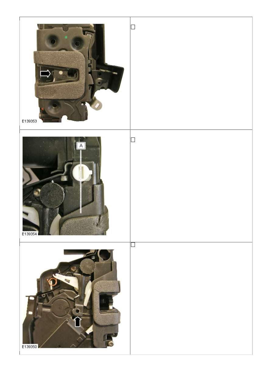
• NOTE: Fully latched position shown

Using a small screw driver or similar, rotate latch claw to
the second fully latched position

• NOTE: Figure A - Child lock off position shown

If testing a rear door latch, ensure that the child lock is
turned to the off position

Confirm that the latch interior release lever is in the
unlocked position as shown

4

1

2
3

4

Whilst the latch is still in its unlocked state, push the latch
interior release lever against its return spring, whilst
simultaneously applying a light pressure to release the
latch claw using a small screw driver or similar

Does the latch claw release
Yes

Latch has passed all tests to confirm its correct function.
DO NOT REPLACE LATCH as part of any attempts to
resolve any locking functionality issues. GO to Pinpoint
Test 

E. 

To confirm vehicle electrical signal is received by

the latch

No

Repeat this test

GO to C4

. If repeat test has confirmed that

the interior release lever will not release the claw when the
latch is in the unlocked state, then replace the latch. If
replacing latch as part of a warranty claim, please quote
reference code INTINOP in the technician comments
section of the warranty claim

PINPOINT TEST D : LATCH MOUNTED DOOR AJAR SWITCH TEST

TEST CONDITIONS

DETAILS/RESULTS/ACTIONS

D1: TEST 4 DOOR LATCH

• NOTE: If a customer is complaining of issues relating to a door ajar signal e.g. door latch won’t lock, or alarm system
triggering (indicated via DTC’s), there may be several components that generate the fault, including

Door Latch ajar switch
Alarm control module
Central junction box
Body wiring harness / connectors
Door wiring harness / connectors

• NOTE: To investigate the functioning of the door ajar switch contained within the door latch, to prove or eliminate the
door latch mounted door ajar switch as the root cause, follow the process below. This will prevent the unnecessary
replacement of a correctly functioning door latch

Remove door trim from door
REFER to: 

Front Door Trim Panel

 (501-05 Interior Trim and

Ornamentation, Removal and Installation) /

Rear Door Trim Panel

 (501-05 Interior Trim and

Ornamentation, Removal and Installation).
Remove module plate / closing panel from door
Remove latch module from door REFER to: (501-14
Handles, Locks, Latches and Entry Systems)

Front Door Latch

 (Removal and Installation),

Rear Door Latch

 (Removal and Installation).

Inspect latch module for any visual damage

5

6

• NOTE: Figure 1 - Unlatched position shown

• NOTE: Figure 2 - First safety latched position shown

• NOTE: Figure 3 - Fully latched position shown

• NOTE: Test will not work if latch is only in first safety latch
position

Using a small screw driver or similar, rotate latch claw to
the second fully latched position (figure 3)

Carry out continuity test between terminals 1 and 4 (left
side)
 or 8 and 4 (right side) with claw closed

Does the continuity test pass?
Yes

The latch ajar switch is working correctly. Do not replace
latch
. Investigate for fault elsewhere in vehicle system

No

Release latch claw and repeat test from step 5 to confirm
result. If this is a repeat test and you are sure that the
ajar switch does not provide continuity when fully latched.
Replace the latch. If replacing latch as part of a warranty
claim, please quote reference code AJARINOP in the
technician comments section of the warranty claim

PINPOINT TEST E : VEHICLE ELECTRICAL SYSTEM TEST

TEST CONDITIONS

DETAILS/RESULTS/ACTIONS

E1: TEST 5 LOCK COMMAND

1

2

3

1

Disconnect electrical connector from latch

Close all vehicle doors apart from door being investigated,
please note which door, left side or right side is under
investigation
Monitor the circuit for momentary power when locking the
vehicle via the key-fob or smart key between terminals 1
and 10 left side
 or 8 and 10 right side

Is there momentary power (for approx 8 seconds) between
terminals 1 and 10 left side or 8 and 10 right side when
locking the vehicle via the key-fob or smart key
Yes

The vehicle electrical system is locking correctly, providing
the signal to the latch. 

GO to E2

.

No

Refer to the electrical circuit diagrams and investigate why
vehicle electrical system is not providing signals to the
latch. Using the manufacturer approved diagnostic system
check for logged DTCs to localize the fault

E2: TEST 6 UNLOCK COMMAND

Monitor the circuit for momentary power when unlocking the
vehicle via the key-fob or smart key between terminals 1
and 9 left side
 or 8 and 9 right side

Is there momentary power (for approx 8 seconds) between
terminals 1 and 9 left side and 8 and 9 right side when
unlocking the vehicle via the key-fob or smart key
Yes

The vehicle electrical system is unlocking correctly,
providing the signal to the latch. Plug electrical connector
back in to latch. Rebuild vehicle and check for correct
operation

No

Refer to the electrical circuit diagrams and investigate why
vehicle electrical system is not providing signals to the
latch. Using the manufacturer approved diagnostic system
check for logged DTCs to localize the fault


Content   ..  580  581  582  583   ..