Frelander 2. Manual - part 491
Module Communications Network - Communications Network
Description and Operation
OVERVIEW
A number of different types of communication network are incorporated into the vehicle wiring harnesses for the
transmission of commands and information between control modules. The configuration installed on a particular vehicle
depends on the model and equipment level.
The communication networks available on the vehicle are:
Local Interconnect Network (LIN) bus
Medium speed Controller Area Network (CAN) bus
High speed CAN bus
Media Orientated System Transport (MOST) ring
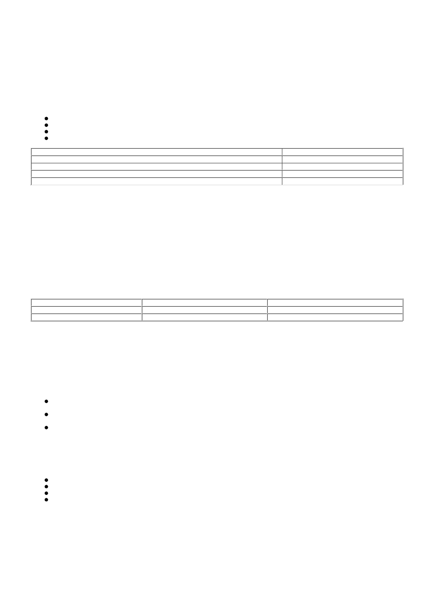
Bus
Baud Rate
LIN bus
9.6 kbits/s
Medium speed CAN bus
125 kbits/s
High Speed CAN bus
500 kbits/s
MOST ring
24 Mbits/s
LOCAL INTERCONNECT NETWORK BUS
The Local Interconnect Network (LIN) bus is a low speed broadcast network that employs master and slave components.
The master component transmits a message along a single wire to the slave components identifying which slave is to
respond. The message has a header (slave identifier) and an empty data field. The identified slave component fills the
data field with the relevant information and returns a message to the master component along the same wire.
CONTROLLER AREA NETWORK BUS
The Controller Area Network (CAN) bus is a high speed broadcast network where control modules automatically transmit
information every few microseconds. Information is broadcast down a pair of twisted wires, known as 'CAN high' and 'CAN
low'. Information is transmitted on the CAN bus as a voltage difference between the 2 wires.
Two CAN bus networks are used on the vehicle; medium speed and high speed, with the Central Junction Box (CJB) acting
as a gateway between the 2 networks. The table below shows the wire colors used on both networks.
Network
High
Low
Medium Speed
Grey and orange
Violet and orange
High Speed
White and blue
White
MEDIA ORIENTATED SYSTEM TRANSPORT (MOST) RING
The Media Orientated System Transport (MOST) ring uses fiber optic cables to transport data and audio signals around the
information and entertainment system. The fiber optic cables are arranged in a ring, with each unit on the ring having a
'MOST in' and 'MOST out' connection.
The MOST ring is a synchronous network. A timing master supplies the clock and all other components on the ring
synchronize their operation to this clock. The timing master for the MOST ring is the integrated control module.
When handling MOST fiber optic cables the following precautions should be observed:
After disconnection of any cables carefully install appropriate dust caps to protect the mating faces of the
connectors from damage and contamination.
Avoid introducing bends of less than 25 mm (0.98 inches) radius or kinks into the fiber optic cable during service or
repair. Tight bends or kinks could impair operation, cause immediate system failure, or future system failure.
Avoid excessive force, strain or stress on the fibers or connectors especially permanent stress after reinstallation.
Ring Break Diagnostics
Incorporated into the Auxiliary Junction Box (AJB) is a Ring Break Diagnostics (RBD) link. The RBD link houses a copper link
which when removed initiates the ring break diagnostics mode. The ring break diagnostics mode allows the technician to
locate an optical fiber break in the MOST ring. To initiate the ring break diagnostics mode, carry out the following process:
Connect the Land Rover approved diagnostic system.
Ensure the vehicle is in power mode 4 or greater.
Remove the RBD link for the length of time specified by the Land Rover approved diagnostic system.
Replace the RBD link.
After approximately 30 seconds a Diagnostic Trouble Code (DTC) will be logged in the Integrated Control Module,
identifying the location of the fault. The DTC can be read and interrogated using the Land Rover approved diagnostic
system.
CONTROL DIAGRAM - LIN BUS (SHEET 1 OF 2)
• NOTE: O = LIN bus