Frelander 2. Manual - part 461
Generator and Regulator - GeneratorI6 3.2L Petrol
Description and Operation
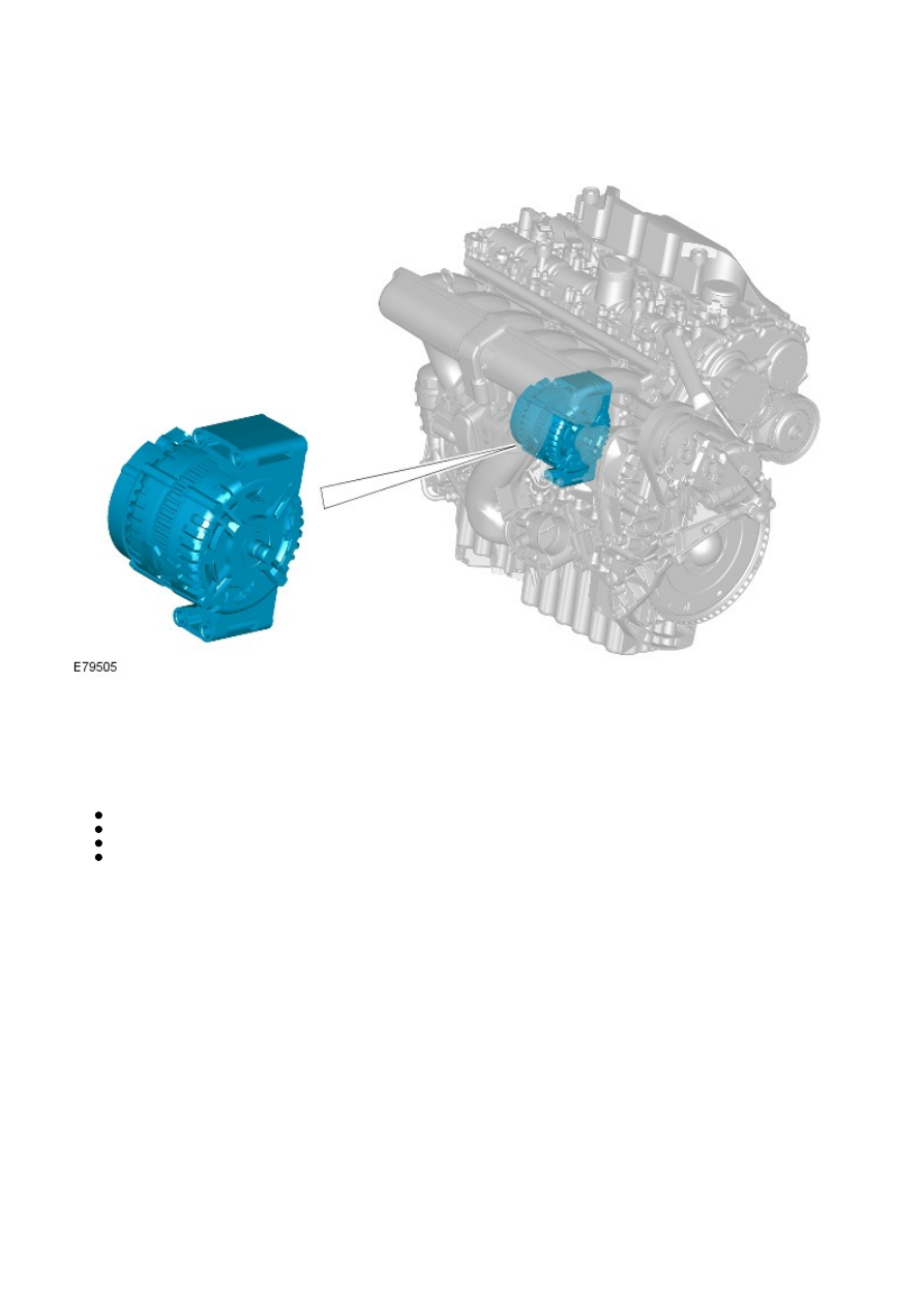
COMPONENT LOCATION
OVERVIEW
The generator used on the Si6 obtains a direct drive from a shaft powered by the crankshaft; a coupling unit attaches the
generator to the shaft. This direct drive arrangement improves the generator's durability by preventing side-loadings,
caused by the tension of a drive belt, acting on the generator's rotor bearing.
The generator has an output of 90/150 amps, and comprises a:
stator,
rotor,
rectifier pack, and
regulator
The stator consists of a flat core pack into which the stator wires are pressed. The rotor comprises a field winding, wound
around an iron core and mounted on a shaft. The rotor is housed within the stator and is mounted on bearings to provide
smooth running and support.
The rectifier converts the Alternating Current (AC) produced in the stator coils into Direct Current (DC), as required by the
vehicle electrical system. The rectifier comprises 6 semi-conductor diodes mounted on a heat sink that dissipates the
resultant heat.
The regulator provides a controlled variable voltage output from the generator. Two electrical terminals are provided on the
outer casing of the generator. One terminal supplies the rectified and regulated DC current from the generator via a large
diameter cable to the battery positive terminal. The second terminal provides the Local Interconnect Network (LIN) bus
connection between the regulator and the Engine Control Module (ECM).
The regulator connects via the LIN bus to the ECM, and the ECM also connects via the high speed Controller Area Network
(CAN) bus to the Central Junction Box (CJB). The CJB contains software maps that provide a mathematical model of
battery electrolyte temperature, and constantly receives information from the ECM regarding the actual battery voltage.
Based on the information received, the CJB then communicates via the high speed CAN bus to the ECM a predicted output
voltage that is required from the regulator to effectively charge the battery.
A corresponding message is then communicated by the ECM to the regulator via the LIN bus, to meet the output voltage
determined by the CJB. This control cycle is repeated under a closed-loop condition.
The LIN bus is also used to communicate a fault in the wiring or the connections from the generator to the ECM. A fault
code will be generated and stored in the ECM and if necessary, the charge warning indicator lamp will be displayed in the
instrument cluster after a short delay. During engine starting the charge warning indicator lamp is illuminated in the
instrument cluster when the ignition is energized, and will extinguish when the engine starts and the ECM detects a
generator output voltage.