Frelander 2. Manual - part 410
Climate Control - Air Conditioning
Description and Operation
COMPONENT LOCATION
Item
Part Number
Description
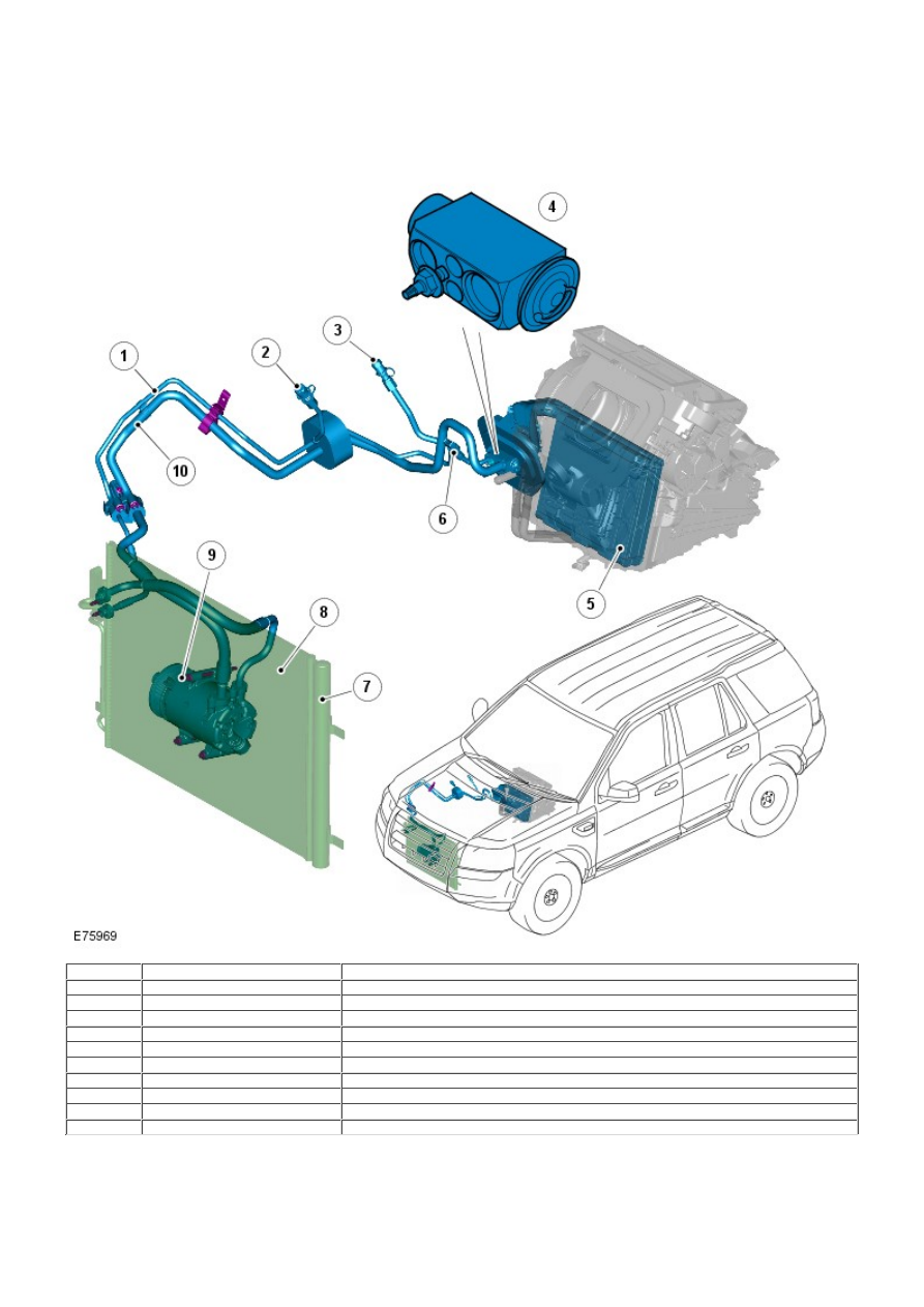
1
-
High pressure line
2
-
High pressure servicing connection
3
-
Low pressure servicing connection
4
-
Thermostatic expansion valve
5
-
Evaporator
6
-
Refrigerant pressure sensor
7
-
Receiver/Drier
8
-
Condenser
9
-
Air Conditioning (A/C) compressor
10
-
Low pressure line
OVERVIEW
The A/C system transfers heat from the cabin to the outside atmosphere to provide the heater assembly with dehumidified
cool air.
The A/C system is a sealed closed loop system, filled with a charge weight of R134a refrigerant as the heat transfer
medium. The refrigerant charge weight for both i6 and TD4 vehicles is 730 g. Oil is added to the refrigerant to lubricate the