Frelander 2. Manual - part 346


  Index      Land Rover     Land Rover Frelander 2 - service repair manual 2006-2010 year


Search            


Content   ..  344  345  346  347   ..


Frelander 2. Manual - part 346


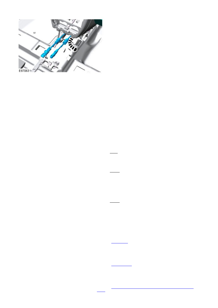
14. NOTE: This step requires the aid of another
technician.

Remove the gear selector cable assembly.

14.

Installation

1. NOTE: This step requires the aid of another technician.

Install the selector cable.

1.

Secure the cables in the clips.

2.

Install the heat shield.

3.

Secure the selector cables.

4.

Install the sealing plate.

Torque: 7 Nm

5.

Install the gearshift lever.

Torque: 10 Nm

6.

Connect the selector cable ball joints.

7.

Install the instrument pack bracket.

Torque: 25 Nm

8.

Secure the drain tube and heater duct.

9.

Install the instrument panel, lower trim panels.

10.

Install the air cleaner assembly.

Refer to: 

Air Cleaner

 (303-12A Intake Air Distribution and Filtering -

I6 3.2L Petrol, Removal and Installation).

11.

Install the floor console.

Refer to: 

Floor Console

 (501-12 Instrument Panel and Console,

Removal and Installation).

12.

Install the driveshaft.

Refer to: 

Driveshaft - Vehicles W ithout: Diesel Particulate Filter

(DPF)

 (205-01 Driveshaft, Removal and Installation).

13.

Automatic Transmission/Transaxle External Controls - Selector Lever Knob,
Boot and Bezel

Removal and Installation

Removal

• NOTE: Make sure that the selector lights function correctly. If the ribbon cable is damaged it will be necessary to remove
the floor console to access the ribbon cable connector on the selector lever assembly.

Position the gearshift lever in NEUTRAL.

1.

Switch the ignition off.

2.


Release the gear lever surround by pulling
upwards firmly at the rear.

3.


Release the locking ring.

4.

5.

6.

7. 

WARNING: The selector lever knob will be

released suddenly, keep face clear during removal.

CAUTION: Make sure the selector lever button is

depressed when removing the selector lever knob.
Failure to follow this instruction may result in damage
to the selector lever assembly.

7.

8.


Content   ..  344  345  346  347   ..