Frelander 2. Manual - part 304


  Index      Land Rover     Land Rover Frelander 2 - service repair manual 2006-2010 year


Search            


Content   ..  302  303  304  305   ..


Frelander 2. Manual - part 304


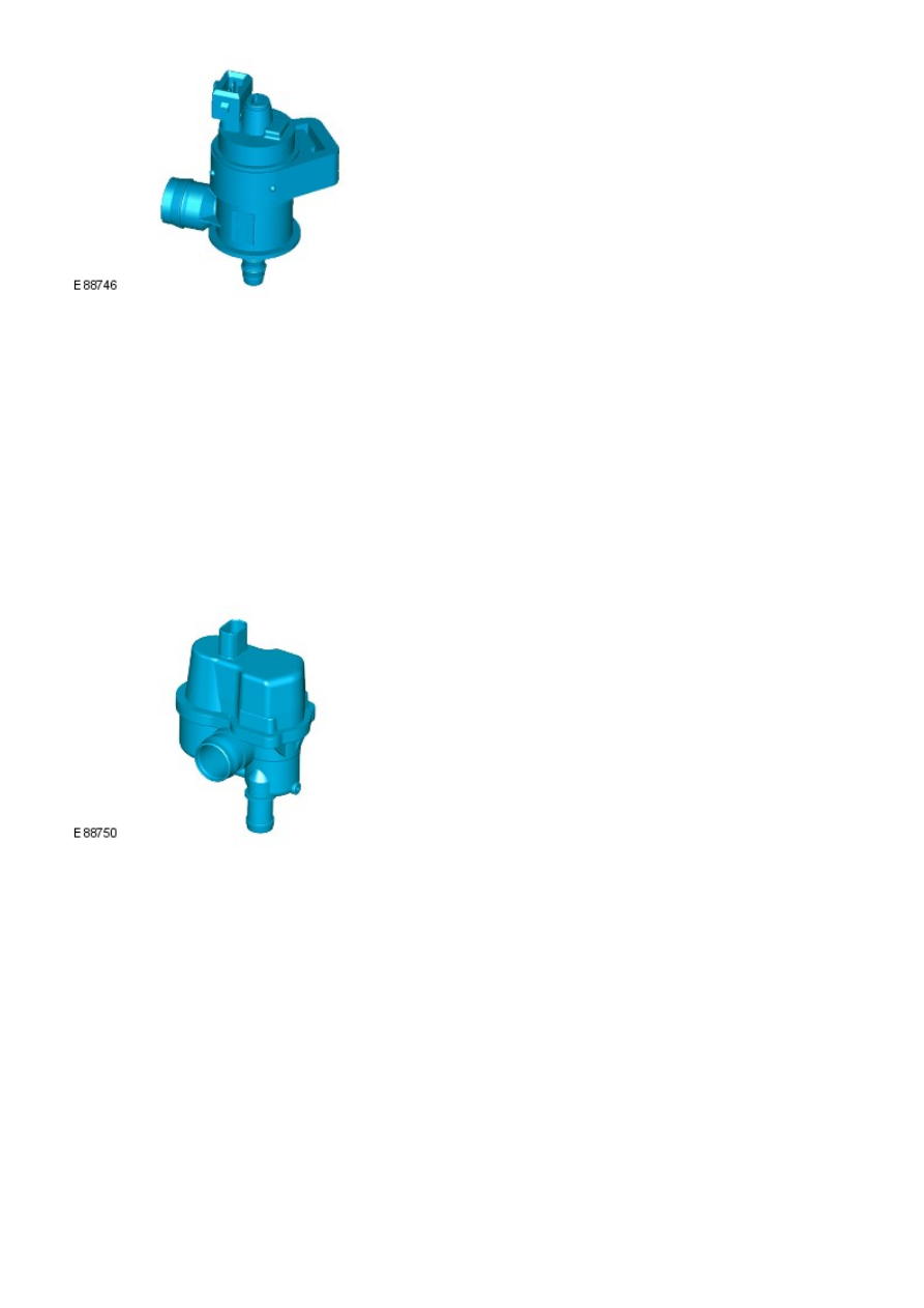
The purge valve is located on a bracket on the inlet manifold, above the electric throttle. The valve has a hose connection
on the bottom which connects into the electric throttle and allows the fuel vapors to be drawn into the inlet manifold. A
larger connection on the side of the valve is connected via a pipe to the evaporative (EVAP) emission canister which is
located in the LH wheel arch behind the liner.

The purge valve controls the flow of fuel vapor from the EVAP canister to the engine intake manifold. Vacuum in the intake
manifold draws the vapor from the canister once the purge valve is open and burns the vapor as part of the combustion
process.

The ECM controls the operation of the purge valve when engine operating conditions are correct to add the fuel vapor to
the combustion process. The valve is an electro-magnetic solenoid valve which receives a fused battery voltage supply via
the main relay. The ECM uses a PWM ground to control the operation of the valve. By altering the frequency of the PW M
ground signal, the ECM can control the rate at which valve is open. This allows the ECM to precisely control the amount of
fuel vapor passing from the EVAP canister.
For additional information, refer to: Evaporative Emissions (303-13, Description and Operation).

The ECM can diagnose faults with the purge valve and store fault related codes. The codes can be read using a Land Rover
approved diagnostic system.

Fuel Tank Leakage Monitoring Module (NAS only)

The fuel tank leakage monitoring module is located in the LH rear wheel arch, adjacent to the EVAP canister. A port on the
side of the module provides for the attachment of a dust filter, through which fresh air is drawn into the EVAP canister. A
port on the underside of the module is connected by a short curved hose to the EVAP canister. This connection allows fresh
air to be drawn into the canister during the purge process and also allows the system to be pressurized by the module for
leakage testing.

The fuel tank leakage monitoring module receives a fused battery voltage supply via the main relay. The module is
connected to the ECM which provides a ground for the module when leak detection is required.

The fuel tank leakage monitoring module comprises an electric air pump, a solenoid valve and a heater element. The air
pump is used to pressurize the EVAP system for leak testing. The solenoid valve is normally open, but closes when
energized by the ECM to close the system to allow it to be pressurized. The PTC heater element is used to warm the pump
before operation.

The fuel tank leakage monitoring system periodically checks the EVAP system and the fuel tank vent system for leaks
when the ignition is off. The system can also be activated for a diagnostic check by the ECM.

The ECM checks for leaks in the system by operating the air pump in the fuel tank leakage monitoring module. The module
air pump is activated and the ECM monitors the current draw on the air pump motor. A reference orifice is provided in the
module which allows the ECM to make a comparison and establish a reference figure for measuring the current draw on the
air pump motor when air is pumped through the orifice.
For additional information, refer to: Evaporative Emissions (303-13, Description and Operation).

The ECM can diagnose faults with the air pump and the solenoid valve and store fault related codes. These codes can be
read using a Land Rover approved diagnostic system.

Speed Control Inhibit Switch

The speed control inhibit switch is attached to the brake pedal bracket, adjacent to the stop lamp switch. W hen the brake
pedal is pressed, a plate on the pedal moves away from the switch plunger allowing the plunger to extend and complete
the switch contacts.

The switch receives a power supply from the CJB which senses the completed ground path when the switch is operated.
The switch has two functions; it is used for starting purposes when the brake pedal must be pressed before engine
cranking is allowed and it is used to suspend speed control operation when speed control is active and the brake pedal is
pressed.

The CJB can diagnose the operation of the speed control inhibit switch and the status of the switch can read using a Land
Rover approved diagnostic system.

Main Relay

The main relay is located in the BJB. The operation of the main relay is controlled by the ECM which provides a ground
path for the main relay coil, energizing the relay and closing the relay contacts.

The main relay supplies battery voltage to the following engine sensors and actuators:

Electric throttle - TP sensor (via ECM)
Fuel injectors
Ignition coils
Coil Capacitor
Variable inlet cam profile switching solenoid - front and rear
Intake tract variable manifold motor
Plenum variable intake manifold motor
HO2S
Purge valve
Fuel tank leakage monitoring pump (NAS only).

Air Conditioning (A/C) Pressure Sensor

The refrigerant pressure sensor provides the Air Temperature Control (ATC) module with a pressure input from the high
pressure side of the refrigerant system. The refrigerant pressure sensor is hardwired to the ECM, which uses the signal to
control operation of the A/C compressor and to calculate the additional load on the engine when the A/C compressor is
operating.

The ECM also broadcasts the refrigerant high pressure value over the high speed Controller Area Network (CAN) bus to the
CJB. The CJB relays the signal to the ATC module over the medium speed CAN bus to increase the amount of recirculated
air if required.

Air Conditioning (A/C) Relay

The A/C relay is located in the BJB. The operation of the A/C relay is controlled by the ECM which provides a ground path
for the A/C relay coil, energizing the relay and closing the relay contacts.

When the relay contacts are closed, battery voltage is supplied via the relay to the A/C compressor clutch. The ECM
controls the operation of the variable displacement compressor using a signal line to the compressor and received signals
from the A/C pressure sensor.

Air Conditioning Compressor Control

Compressor displacement is controlled by the ECM based on current evaporator temperature and target evaporator
temperature signals received from the ATC module. From these values the ECM calculates the required compressor
displacement and provides a Pulse W idth Modulated (PWM) signal to the compressor solenoid valve. The compressor
solenoid valve is mounted on the rear of the compressor and interprets the PW M signal as a displacement value and alters
the position of the internal swash plate accordingly.

The ECM will also reduce the displacement of the A/C compressor to its minimum level if 'full throttle' or automatic
transmission 'kick down' is requested. This feature is not present on Gulf specification vehicles. Compressor clutch
engagement is controlled by the ECM.

Engine Cooling Fan Control

The ECM has a hardwired connection with the cooling fan control module. The ECM outputs a PW M signal to the fan control
module which relates to the required fan speed. The fan speed is determined by factors such as engine coolant
temperature and A/C operation. The fan control module reacts to the received signal by controlling the operating voltage of

the fan motors. The fan control module confirms the fan speed operation on the same connection back to the ECM.

Starter Motor Relay

The starter motor relay is located in the BJB. The operation of the starter motor relay is controlled by the ECM which
provides a ground path for the relay coil, energizing the relay and closing the relay contacts. W hen the relay contacts are
closed, battery voltage is supplied, via the starter motor relay, to the starter module solenoid coil. The starter solenoid is
energized and connects the starter motor with a direct battery feed to operate the starter motor.

Once the engine has started, the ECM removes the starter motor relay ground, opening the relay contacts and terminating
the battery feed to the starter solenoid, which in turn stops the operation of the starter motor.
For additional information, refer to: Starting System - 3.2L (303-06, Description and Operation).

Fuel Pump Module

The fuel pump is controlled by the FPDM which in turn is controlled by the ECM. The FPDM provides positive and negative
feeds to the fuel pump motor which is controlled with a PWM output. The fuel pump is run for 2 seconds to prime the fuel
system once ignition on is sensed by the ECM.
For additional information, refer to: Fuel Tank and Lines (310-01, Description and Operation).

Malfunction Indicator Lamp (MIL)

The MIL is located in the instrument cluster and is illuminated by a CAN message from the ECM when an emission related
fault occurs. The ECM also illuminates the MIL when requested to do so by the TCM and to perform a bulb check when the
ignition is switched on. There is no MIL illumination for non emission related engine management faults. All engine faults
are recorded with a Diagnostic Trouble Code (DTC) which can be retrieved using a Land Rover approved diagnostic system.
For additional information, refer to: Electronic Engine Controls - 3.2L (303-14, Diagnosis and Testing).

Generator Feedback Signal

The generator has a Local Interconnect Network (LIN) bus connection direct to the ECM. The LIN bus is used by the ECM to
request voltage for battery charging and to monitor the fault status of the generator.

PRINCIPLES OF OPERATION

Starting Process

The ECM will only allow engine crank, spark and injector functions when the following conditions are met:

A hardwired Park/Neutral signal is received from the Transmission Control Module (TCM)
A hardwired ignition signal is received from the CJB
A hardwired crank request signal is received from the CJB
Encrypted data exchange between the instrument cluster and the ECM is verified.

Before the CJB will send the hardwired ignition signal, it must satisfactorily complete the following:

Exchange encrypted data with the start control module to validate the remote handset.

Additionally, before the CJB will send the hardwired crank request signal it must receive the following signals:

Brake signal from the speed control inhibit switch
Hardwired transmission in Park (P) or Neutral (N) signal from the selector lever assembly.

With the remote handset inserted in the start control module and the stop/start button is pressed, the start control
module issues battery voltage high signal on the LIN bus connection to the CJB and the fuel pump is run for 2 seconds to
prime the fuel system. The CJB uses this signal together with the stop lamp switch signal and issues a crank request
message on the high speed CAN bus to the ECM.

The ECM, on receipt of the crank request message, then provides a power and ground supply to the starter relay in the
BJB, closing the relay contacts. Battery voltage is supplied via a fuse through the starter relay and is passed to the starter
motor solenoid coil. The coil is energized, closing the solenoid contacts and allowing a fuse battery voltage supply direct
from the battery to operate the starter motor and crank the engine and simultaneously switch the fuel pump on.

The ECM operates the starter motor until the engine starts which is determined by the engine speed exceeding a
pre-determined value.

Auto Start

The ECM has an auto start function which allows the engine to continue cranking if the stop/start button is released. The
starter motor will operate until the engine starts or a pre-determined period of time has elapsed which is based on engine
coolant temperature. Low engine coolant temperatures allow longer crank times. If the engine does not rotate or the
engine speed is low, the ECM removes the power supply and ground from the starter relay stopping the crank process.

Start Prevention

Operation of the starter motor will not be allowed or will be interrupted if:

the engine is running and the engine speed has exceeded a predetermined speed
the encrypted data exchange between the instrument cluster, ECM, CJB and start control module has failed to
identify the remote handset
the gear selector lever is not in the park 'P' or neutral 'N' position. The signal is determined from a signal from the
TCM and also the transmission mounted position switch
the brake pedal is not pressed.

Engine Stop Process

To stop the engine the stop/start button must be pressed. Forcibly removing the remote handset from the start control
module will not stop the engine. On models with automatic transmission, once the engine has stopped the remote
handset will not be released by the start control module until the transmission selector lever is in the Park (P) position.

Throttle Control

The ECM controls the positioning of the throttle disc in the electric throttle using information from the APP sensor and the
TP sensor. Data from the A/C pressure sensor, TCM, ECT sensor, MAF sensor and the MAP/IAT sensor is also used to
determine the correct throttle control.

The two Hall effect sensors in the TP sensor are designated 1 and 2. Both sensors output an increasing voltage as the
throttle disc angle increases. Small air flows through the throttle require comprehensive regulation, therefore the voltage
rise in one of the sensors increases more quickly than the other sensor which gives accurate control of the throttle and
ensure the throttle disc is in the correct position.

The ECM monitors the signals from both sensors to ensure they are within the minimum and maximum thresholds and that
the signals correspond to the same throttle disc position. If there is a difference in the signals the ECM uses a default
throttle signal calculated from the electric throttle load, engine speed and air pressure and temperature signals. The
sensor whose output signal is closest to the calculated throttle disc angle will be used as the correct output. A fault code
will be recorded for the other sensor and this can be read using a Land Rover approved diagnostic system. The ECM then
monitors the remaining sensor output signal and compares it against the calculated value. If a difference in the
comparison occurs the ECM will discount the output from both sensors and disable the electric throttle control and revert to
a limp home mode. The throttle disc has springs for opening and closing and the ECM can measure the load applied by
these springs for a load signal. If a fault occurs which prevents the damper motor from being operated, the springs return
the throttle disc to a position which allows a throttle opening large enough to allow the vehicle to driven, but with reduced
drive ability.

Throttle Adaptions

The ECM has a learning adaption which allows the ECM to calculate the precise control required for the electric throttle
damper motor. The adaption process is performed when the ignition is on and the engine is not running. The throttle disc
is moved by the damper motor to the fully closed position and the ECM records the values output by the TP sensor
potentiometers.

If the permanent battery supply to the ECM has been removed, then previous adaptions will have been lost. If adaptions
are stored, then the ECM compares the stored adaption values with the current throttle angle and uses an average of the
stored and current values to create the new adaption value.

If the electric throttle unit has been replaced, the power supply must be removed from the ECM to erase all previously
stored adaption values.

Fuel Pressure Regulation

Fuel pressure regulation is controlled by the ECM to respond to fuel pressure demand and provides stepless control of the

pump output using the FPDM to control the pump operation. The ECM can vary the fuel pressure to between 55.1 lbf/in

2

(3.8 bar) and 72.5 lbf/in

2

 (5 bar). The high pressure is only used in extreme conditions such as heavy engine loads and

engine starts.

The ECM uses the signals from the fuel rail pressure/temperature sensor to determine information regarding the pressure
and temperature of the fuel and provide precise injection periods, improving engine starting under all conditions. The
advantage of controlling the fuel pump output pressure are that pump power consumption is reduced, lowering the load on
the power supply system and reducing fuel consumption, improved service life of the pump and reduced fuel pump noise.

• NOTE: When the ignition is switched off the FPDM reduces the fuel line pressure regulation to 29 lbf/in

2

 (2 bar) to help

reduce injector leakage.

Knock Control

Knock occurs in a cylinder when the fuel and air self ignites at the wrong timing. This can occur either before or after the
spark is produced. The fuel mixture can ignite in different areas of the combustion chamber and results in a fast
combustion process creating several separate fuel combustions which together combine to produce a mechanical knocking
sound. The sounds produce a certain type of vibration through the engine cylinder block and these are detected by the
knock sensors. The two knock sensors detect knocks on cylinders 1, 2 and 3 and 4, 5 and 6 respectively.

The vibrations act upon the peizo crystals within the sensors which results in a voltage being produced which is sensed by
the ECM. The ECM, using the CMP sensors and the CKP sensor, can determine which cylinder(s) are knocking. The ECM is
able to filter the signal to detect vibrations created during normal engine operation and discard them from the knock
detection. The ignition timing is gradually advanced until the knocking is detected once again.

Once the ECM has determined knocking is occurring using other inputs such as catalytic converter temperature for example
in addition to the signals from the knock sensors, it first retards the ignition timing and subsequently richens the air/fuel if
required.

Variable Camshaft Timing (VCT) Control

The inlet camshaft is controlled by the ECM using the VCT solenoid. The exhaust camshaft is fixed and its timing cannot
be changed.

Both camshafts are driven indirectly from the crankshaft via a chain. The chain is driven from a shaft in the gear housing
assembly.
For additional information, refer to: Engine - 3.2L (303-01, Description and Operation).
The VCT allows the ECM to adust the inlet camshaft position in relation to the crankshaft, altering the timing of the
opening and closing of the inlet and exhaust valves relative to the crankshaft position. This allows the ECM to provide
increased engine performance, improved idle quality and reduced emissions.


Content   ..  302  303  304  305   ..