Frelander 2. Manual - part 302


  Index      Land Rover     Land Rover Frelander 2 - service repair manual 2006-2010 year


Search            


Content   ..  300  301  302  303   ..


Frelander 2. Manual - part 302


The ECT sensor is located in the thermostat housing, on the front of the engine, below the inlet manifold. The ECT sensor
is a thermistor type sensor used by the ECM to monitor the engine coolant temperature. The ECM uses the temperature
information for the following functions:

regulate the injection period
set engine idle target speed
control the engine cooling fan(s)
determine operation of the A/C compressor
determine operation of the purge valve and catalytic converter heating function.

The sensor is a Negative Temperature Co-efficient (NTC) thermistor element. The element resistance decreases as the
sensor temperature increases. The ECM supplies the sensor with a 5V reference voltage and a ground and measures the
returned signal as a temperature.

The ECT sensor is important to the correct running of the engine as a richer mixture is required at low engine coolant
temperatures for efficient starting and smooth cold running. As the engine coolant temperature increases, the ECM uses
the temperature signal from the sensor to lean off the fuel mixture to maintain optimum emissions and performance.

The ECM monitors the ECT sensor for faults and can store fault related codes. These can be retrieved using a Land Rover
approved diagnostic system. If the ECT sensor fails, the ECM uses a default value of 90°C (194°F). The electric fan control
module is sent a default coolant temperature value of 105°C (221°F) and switches the cooling fan on permanently.

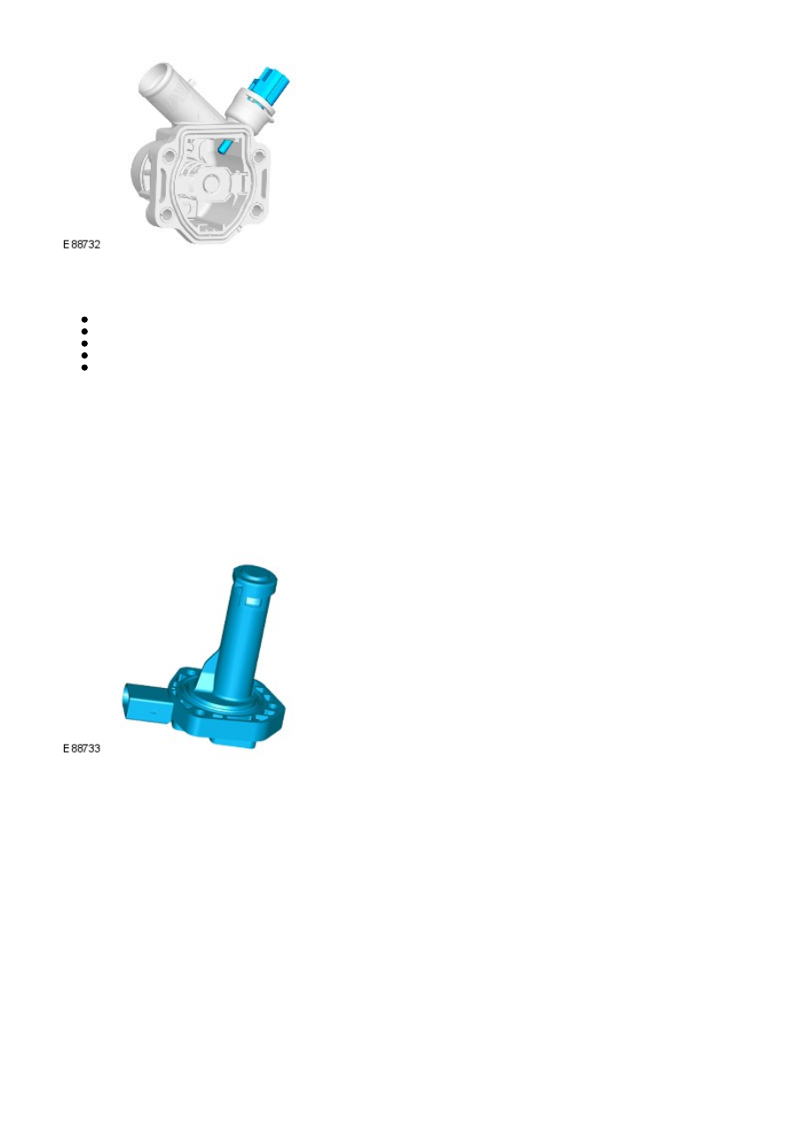
Engine Oil Level/Temperature Sensor

The engine oil level/temperature sensor is located on the underside of the engine and is secured in the engine oil pan with
3 screws and is sealed with an O-ring seal. The ECM supplies the sensor with a 5V reference voltage and two wires supply
the temperature and oil level signals back to the ECM.

Two types of engine oil level/temperature sensor are used. On earlier models a capacitive oil level sensor is fitted and was
replaced by an ultrasound level sensor on later models. The principle of the temperature sensor is the same in both sensor
types. The sensors can be identified by differences in the sensor housings; the capacitive sensor has the electrical
connector moulded square to the base of the sensor, the ultrasonic sensor has the connector moulded at a slight angle to
the base of the sensor.

The ECM uses both the oil level and temperature signals to calculate the oil level. Temporary oil level changes caused by
hill driving or cornering are taken into account by the ECM using additional information such as vehicle speed and engine
load.

Engine Oil Level Sensor - Capacitance Type

The engine oil level sensor comprises two capacitive gauge elements. These measure the resistance to electrical current
passing through the engine oil.

There are two capacitors, one measuring the permittivity of the oil and a second with two plates set vertically measuring
the height. The second capacitor will have a proportion of oil and air between the plates and since the permittivity of air is
different to that of oil, the permittivity reading will change as the level of oil decreases and the air between the plate gap
increases. This permittivity reading is compared to that of the oil (taken by the first capacitor) and an oil level is derived.

Engine Oil Level Sensor - Ultrasound Type

The engine oil level sensor uses an ultrasonic pulse, which is reflected back from the surface of the oil. The time it takes
for this signal to return to the sensor is turned into a PWM signal and is sent to the ECM. The ECM determines the time
taken for the ultrasonic pulse signal to be received and calculates it into an oil level figure.

Engine Oil Temperature Sensor

The engine oil temperature sensor is a Positive Temperature Co-efficient (PTC) thermistor element. The element resistance
increases as the sensor temperature decreases. The ECM supplies the sensor with a 5V reference voltage and a ground and
measures the returned signal as a temperature. A low oil temperature will result in a low voltage being returned to the
ECM and high oil temperature will return a high voltage reading.

The ECM monitors the engine oil level/temperature sensor for faults and can store fault related codes. These can be
retrieved using a Land Rover approved diagnostic system. If the sensor fails, the ECM uses the engine coolant temperature
sensor signal value as a substitute.

Manifold Absolute Pressure (MAP) Sensor

The MAP sensor is located in the lower part of the intake manifold. The MAP sensor measures the absolute pressure in the
intake manifold. The sensor is a semi-conductor type sensor which responds to pressure acting on a membrane within the
sensor, altering the output voltage. The sensor receives a 5V reference voltage and a ground from the ECM and returns a
signal of between 0.5 - 4.5V to the ECM. A low pressure returns a low voltage signal to the ECM and a high pressure
returns a high voltage.

The MAP sensor detects quick pressure changes in the intake manifold after the electric throttle. The signal is used in
conjunction with the MAF sensor signal to calculate the injection period.

The ECM monitors the engine MAP sensor for faults and can store fault related codes. These can be retrieved using a Land
Rover approved diagnostic system. If the sensor fails, the ECM uses the MAF/IAT sensor signal value as a substitute.

Electric Throttle

The electric throttle is located at the entrance of the intake manifold and is secured to the manifold with four Torx head
bolts. The throttle also provides for the connection of the air cleaner housing outlet pipe which is secured to the throttle
body with a clip.

The electric throttle comprises the throttle body, a round throttle disc which is actuated by a damper motor and a throttle
position sensor. The electric throttle is controlled by the ECM and receives positional signals from the TP sensor. If a
failure of the motor occurs, the throttle disc is returned to its closed position by the springs, with limited engine speed
available to the driver.

Spindle Damper Motor

The motor is a DC damper motor which drives a gear wheel and two springs; one for opening and one for closing. The
motor rotates the spindle to which the throttle disc is attached. PW M signals from the ECM control the damper motor to
adjust the position of the throttle disc, regulating the amount of air entering the inlet manifold for combustion.

Movement of the motor is achieved by changing the polarity of the power supply to the DC motor, allowing it to be
operated in both directions. The throttle disc and the motor has two maximum positions; throttle disc closed which allows
minimal air flow through the electric throttle into the intake manifold and throttle disc open which allows maximum air flow

into the intake manifold.

Throttle Position (TP) Sensor

The TP sensor is housed in the electric throttle assembly and is used to check the position of the throttle disc. Two
permanent magnets in the sensor connected to the throttle disc affect two Hall effect sensors. As the spindle is rotated
the magnets rotate around the Hall effect sensors and produce offset analogue signals back to the ECM. The ECM
compares these signals to stored values to ensure that they show an accurate throttle disc position. The offset signals are
that one Hall effect sensor produces a higher voltage as the throttle angle increases and the other sensor produces a
lower voltage as the throttle angle increases.

The ECM performs a self test and a calibration routine on the throttle disc position at each ignition cycle. This is achieved
by the ECM powering the damper motor to fully close the throttle disc and then fully open the throttle disc.

The ECM monitors the DC damper motor and the TP sensor for faults and can store fault related codes. These can be
retrieved using a Land Rover approved diagnostic system.

Accelerator Pedal Position (APP) Sensor

The APP sensor is located on the accelerator pedal. The sensor comprises a plastic housing which contains two
potentiometers and an analogue/digital converter. The potentiometers are connected to a common shaft which is actuated
by movement of the accelerator pedal.

The APP sensor provides the ECM and the CJB with information relating to the position of the accelerator pedal. The ECM
uses this information to actuate the damper motor in the electric throttle assembly to move the throttle disc to the correct
angle in relation to the pedal position.

The APP sensor receives a fused 12V supply from the CJB, which is controlled by the ignition relay in the BJB. The CJB also
provides the sensor with a ground. The sensor provides two outputs; the analogue output is transmitted directly to the
CJB, which in turn issues the signal to the ECM on the CAN bus, the second output is the Pulse W idth Modulation (PW M)
signal which is transmitted directly to the ECM. Both the analogue and PWM signals transmit the same positional
information.

The ECM uses the PWM signal to calculate the required position of the electric throttle disc in the electric throttle. In the
event of a failure of the PWM signal, the ECM uses the analogue signal received from the CJB as a replacement. If the
analogue signal is also incorrect or missing, the ECM limits the maximum engine speed to 2000 rpm.

The PWM and the analogue signal are used for diagnosing faults with the APP sensor. If the ECM detects a difference
between the analogue and PWM signals a fault code is stored. The ECM will use the signal with the lowest value for
electric throttle control. The APP sensor position and any stored fault codes can be read using a Land Rover approved
diagnostic system.

Heated Oxygen (HO2S) Sensors

Four HO2S are used by the ECM to measure the oxygen content of the exhaust gasses leaving the engine. Two upstream
sensors measure the gasses before they pass through the catalytic converter and two additional downstream sensors
measure the gasses after they have passed through the catalytic converter.

The HO2S receive a fused power supply from the main relay in the BJB. Each HO2S is also connected to the ECM on three
wires which provide a PWM control of the sensor heating coil, a ground and a signal line.

HO2S Preheating

The HO2S (often referred to as a Lambda (λ) sensor) only operates efficiently at temperatures above 300°C (572°F). The
normal operating temperature is between 300°C and 850 °C (572°F and 1562°F) and the HO2S is electrically preheated so
it reaches the optimum working temperature quickly. Another reason for the preheating is to maintain a normal operating
temperature to prevent condensation which could damage the sensor.

The sensor heating coil is a PTC resistor. The heating coil is supplied with battery voltage via the main relay and provided
with a ground by the ECM. When the ECM provides the ground the current will pass through the coil. When the sensor is
cold, the resistance through the PTC resistor is low and a high current will pass through the coil. The ECM provides a PWM
ground initially. As the PTC resistor heats up the resistance increases reducing the current flow. This is sensed by the ECM
which gradually reduces the PW M ground to a continuous ground.

The coil is heated immediately following an engine start for a period of approximately 20 seconds and also during low load
conditions when the temperature of the exhaust gasses is insufficient to maintain the optimum sensor temperature. The
ECM controls the application of the PW M signal to prevent sensor damage due to thermal shock caused by the sensor
heating too quickly. The ECM can diagnose faults in the heater coil and record fault codes which can be retrieved using a
Land Rover approved diagnostic system.

Upstream HO2S

Two upstream HO2S are used and are located in each exhaust manifold, between the engine and the catalytic converter.
The HO2S comprises a solid electrolyte Zirconium dioxide cell surrounded by a gas permeable ceramic. The output voltage
from the sensor is dependent on the level of O

2

 passing through the permeable ceramic coating. Nominal voltage for λ=1

is 300 to 500mV. As the fuel/air mixture becomes richer (λ<1) the voltage rises to up to 900mV. As the mixture becomes
weaker (λ>1) the voltage falls towards 0mV.

The upstream HO2S is used by the ECM to monitor the oxygen content of the exhaust gasses leaving the engine before
they reach the catalytic converter. The ECM will check the output from the HO2S to determine the combustion mixture and
ensure λ=1 is obtained. λ=1 is the optimum air/fuel ratio which relates to a mixture of 14.7 kg air per 1 kg of fuel
(14.7:1).

The HO2S uses current regulation and outputs a linear signal dependent on the ratio of exhaust gas oxygen to ambient
oxygen. The oxygen content of the exhaust gasses is measured by comparing it with ambient air drawn into the HO2S.

Downstream HO2S

Two downstream HO2S are used and are located in the each exhaust system after the starter catalytic converter. The
downstream HO2S are used by the ECM to monitor the oxygen content of the exhaust gasses leaving the catalytic
converter. The ECM can use this information to check (when the conditions for catalyst diagnostics have been met) for
correct operation of the catalytic converter.


Content   ..  300  301  302  303   ..