Frelander 2. Manual - part 244


  Index      Land Rover     Land Rover Frelander 2 - service repair manual 2006-2010 year


Search            


Content   ..  242  243  244  245   ..


Frelander 2. Manual - part 244


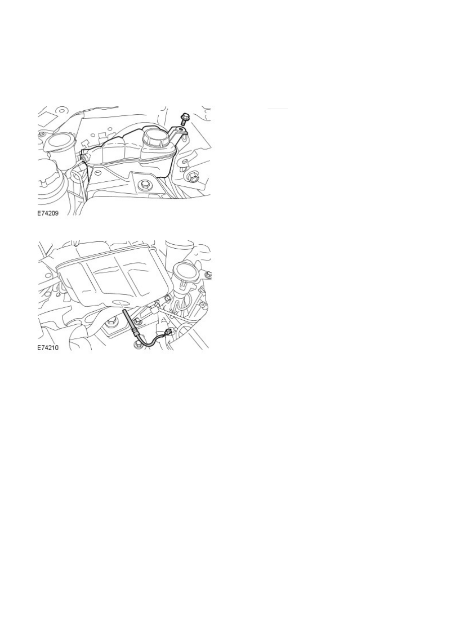
Engine Cooling - TD4 2.2L Diesel - Engine Coolant Level Switch

Removal and Installation

Removal

• NOTE: Removal steps in this procedure may contain installation details.

Torque: 10 Nm

1.

2.

Installation

To install, reverse the removal procedure.

1.

Fuel Charging and Controls - I6 3.2L Petrol -

General Specification

Item

Specification

Recommended fuel:
UK, Europe

91 - 98 RON

USA

Minimum 91 CLC or AKI

Fuel injectors:
Make

Denso

Fuel Pressures

Component

bar

psi

Fuel rail - normal operating conditions - not using IDS

3.7

54

Fuel rail - normal operating conditions - using IDS

4.8

68

Fuel rail - engine off - using IDS

2.8 to 3.2

40 to 46

Fuel rail - cold start - using IDS

6.5

94

Torque Specifications

Description

Nm

lb-ft

Fuel injector clamp plate bolts

6

5

Fuel pressure regulator bolts

6

5

Fuel pump drive module retaining bolts

10

7

Fuel rail bolts

10

7

Fuel rail pressure sensor

6

5

Schreader valve bolts

6

5

Throttle body screws

8

6

Fuel Charging and Controls - I6 3.2L Petrol - Fuel Charging and Controls

Description and Operation

Authoring Template

COMPONENT LOCATION

Item

Part Number

Description

1

-

Fuel rail

2

-

Fuel injector

3

-

Fuel line

4

-

Fuel rail pressure and fuel temperature sensor

OVERVIEW

The fuel pump module, located in the fuel tank, is electronically regulated by the Engine Management System (EMS) to
provide controlled pressure in the fuel rail
For additional information, refer to: 

Fuel Tank and Lines

 (310-01A Fuel Tank and Lines - I6 3.2L Petrol, Description and

Operation).
.

Supplying the correct amount of fuel as required by the engine at any given moment, eliminates the requirement for
additional pipes returning excess fuel to the fuel tank. The benefits of this type of system are:

Reduced load on the electrical system

Improved fuel economy
Eliminates the effects of fuel pressurization and depressurization
Eliminates the effects of engine-heat causing extra fuel vapor being generated in the fuel tank by returning fuel

Closed-loop Pulse Width Modulation (PWM) control, of the fuel pump module, via the Engine Control Module (ECM)
regulates the amount of fuel supplied by the fuel pump to the fuel rail. The ECM receives signals from the combined fuel
rail pressure and fuel temperature sensor, located on the fuel rail to indicate the pressure of fuel in the fuel rail. In
response to these signals, plus other engine and driver demand signals, the ECM calculates the amount of fuel required
and requests the fuel pump module to vary the fuel pump delivery to suit the engine’s requirements.
For additional information, refer to: 

Electronic Engine Controls

 (303-14A Electronic Engine Controls - I6 3.2L Petrol,

Description and Operation).

The fuel pump maintains a fuel rail pressure 3.8 bar above manifold depression under normal operating conditions, though
this is programmed to rise to 4.2 bar in response to either:

cold start conditions, to improve fuel vaporization
cold fuel conditions, as the colder the fuel the higher its viscosity

The fuel rail has an integrated pulsation damper and a connection for draining the fuel system.

The injectors supplied by the fuel rail; each have 4 micro-nozzles capable of injecting up to 18 mg of fuel under high-load
conditions, the injectors also provide precision fueling across all engine speed and load conditions.


Content   ..  242  243  244  245   ..