Frelander 2. Manual - part 197


  Index      Land Rover     Land Rover Frelander 2 - service repair manual 2006-2010 year


Search            


Content   ..  195  196  197  198   ..


Frelander 2. Manual - part 197


Item

Part Number

Description

A

-

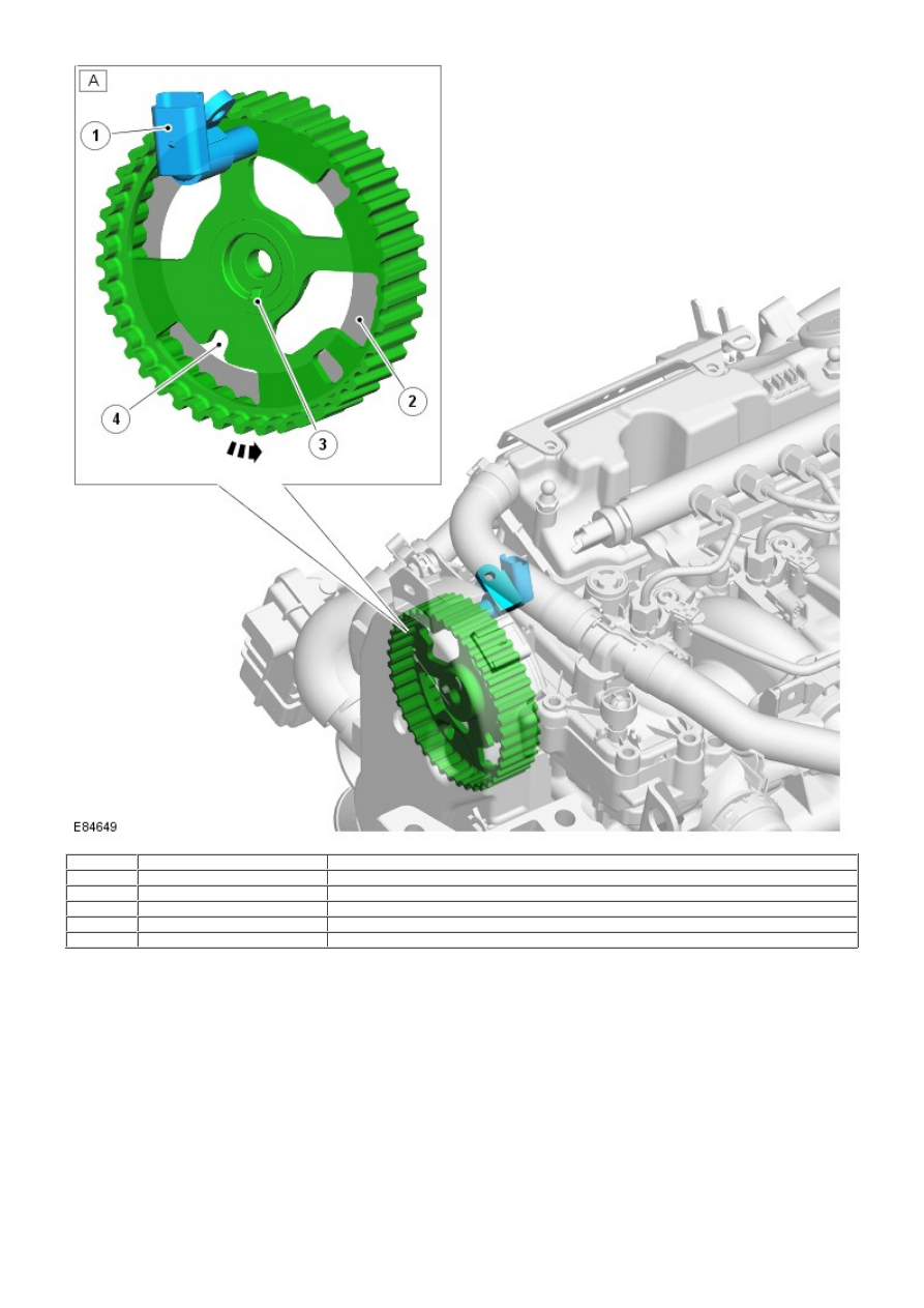
Rear view of exhaust camshaft pulley

1

-

CMP sensor

2

-

CMP target area

3

-

Camshaft pulley key slot

4

-

Camshaft timing pin location

The CMP sensor is mounted at the front of the engine behind the exhaust camshaft drive pulley. The sensor tip protrudes
through a hole in the cylinder head cover, and is positioned close to the camshaft pulley target area. The position of the
sensor to the camshaft pulley is adjustable.

For further details on setting the CMP sensor gap, refer to the relevant Service Repair Procedures (SRP) manual.

The sensor is a variable reluctance sensor that provides a signal of No. 1 cylinder camshaft position to the ECM. The
information is used by the ECM to determine the precise moment for injection during engine cranking.
For additional information, refer to: Electronic Engine Controls (303-14 Electronic Engine Controls - 2.2L Duratorq - Td4,
Description and Operation).

Intake and Exhaust Valves

Item

Part Number

Description

1

-

Lower spring guide

2

-

Valve spring

3

-

Upper spring guide

4

-

Split taper collets

5

-

Intake valve

6

-

Exhaust valve

The cylinder head incorporates 2 overhead camshafts operating 4 valves per cylinder, via steel roller rockers with hydraulic
lash adjusters.

The intake valve is produced from a single material having a head diameter of 24.70 mm (0.972 in). The exhaust valve
head and stem are produced from different materials that are friction welded together. The exhaust valve head diameter is
22.33 mm (0.879 in). Both the intake and exhaust valve stem diameters are 6.0 mm (0.236 in).

The 16 valve springs are single helical-coil type, and manufactured from 3 mm (0.118 in) spring steel. Each spring is
installed over a valve stem, with the spring located in a lower spring guide that seats against the cylinder head. The
spring upper end locates in an upper spring guide that is attached to the valve stem with 2 split taper collets. The 2 taper
collets are formed with grooves on the internal bore and locate in formed grooves in the upper valve stem. The lower
spring guide also forms the valve stem seal and is installed with an O-ring.

Hydraulic Lash Adjusters and Roller Finger Rockers

Item

Part Number

Description

1

-

Hydraulic lash adjuster

2

-

Roller finger rocker

The 16 valves are operated with roller-type finger rockers and hydraulic lash adjusters, actuated by the camshaft lobes.
One end of the finger rocker rests on the end of the valve stem; the other end is attached to a hydraulic lash adjuster. The
center of the finger rocker is formed with a roller that remains in contact with the camshaft lobe.

Typical Hydraulic Lash Adjuster

Item

Part Number

Description

1

-

Oil passage

2

-

Roller finger rocker

3

-

Camshaft

4

-

Cylinder head

5

-

Valve

6

-

Hydraulic lash adjuster

7

-

Plunger spring

8

-

High-pressure chamber

9

-

Ball valve

10

-

Plunger

11

-

Reservoir chamber

12

-

Oil passage

13

-

Hydraulic lash adjuster body

14

-

Plunger cap

Movement of the camshaft lobe presses down on the finger rocker roller, and consequently, the hydraulic lash adjuster and
valve mechanism are forced down together. The respective valve is forced down against valve spring pressure, and the
hydraulic plunger is also forced into an oil chamber in the cylinder head. This type of valve actuation minimizes friction
between the valve operating components, and also eliminates the requirement for manual adjustment.

The body of the hydraulic lash adjuster contains a plunger, and 2 chambers for oil feed and pressurized oil. The
pressurized oil is supplied to the lash adjuster via the cylinder head oil gallery, and through a hole in the side of the lash
adjuster body. The oil passes into a feed chamber within the lash adjuster, and then through to a separate pressure
chamber via a one-way ball valve.

Oil flow from the pressure chamber is determined by the clearance between the lash adjuster outer body and the center
plunger. Oil escapes up the side of the plunger each time the lash adjuster is operated. The downward pressure on the
plunger forces a corresponding amount of oil in the lash adjuster body to be displaced.

As the camshaft lobe rotates further, downward pressure on the camshaft and finger rocker is removed. The lash adjuster
plunger is forced up by the oil pressure contained in the pressure chamber. The pressure is not sufficient to affect valve
operation, but is sufficient to eliminate the clearance between the finger rocker and top of the valve stem.

Cylinder Head Cover

Item

Part Number

Description

1

-

PCV valve

2

-

Crankcase ventilation hose connection

3

-

Engine cover fixing

4

-

CMP sensor location

The 'L' shaped cylinder head cover is installed over the structural camshaft cover and encloses the exhaust camshaft, and
the intake and exhaust camshaft drive openings. A preformed gasket and the PCV component O-rings provide the seal
between the 2 covers.

The cylinder head cover is manufactured from composite materials, and incorporates the Positive Crankcase Ventilation
Valve (PCV), safety valve and crankcase ventilation connections.
For additional information, refer to: 

Engine Emission Control

 (303-08B Engine Emission Control - TD4 2.2L Diesel,

Description and Operation).

The cylinder head cover provides the location for the CMP sensor, and 3 of the acoustic engine cover fixings.

Thermal Control Module


Content   ..  195  196  197  198   ..