Frelander 2. Manual - part 189


  Index      Land Rover     Land Rover Frelander 2 - service repair manual 2006-2010 year


Search            


Content   ..  187  188  189  190   ..


Frelander 2. Manual - part 189


Engine - TD4 2.2L Diesel - Engine

Description and Operation
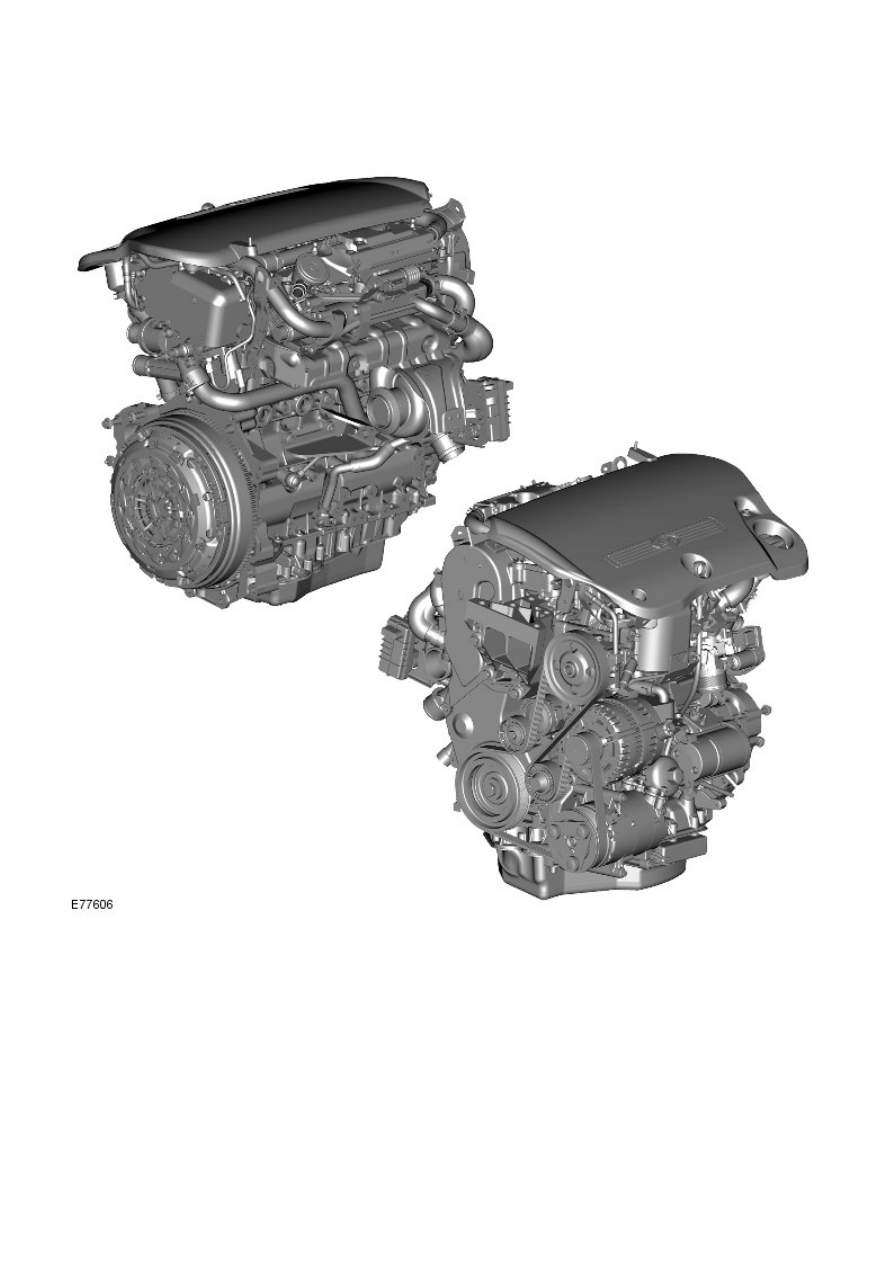
EXTERNAL VIEW

OVERVIEW

• NOTE: Freelander 2 features a new TD4 diesel engine. This TD4 diesel engine is not previously used by Land Rover, and
must not be mistaken for the Td4 diesel engine used with the previous Freelander model.

The new TD4 diesel engine may also be referred to, and appear in text as the 2.2L Duratorq-TDCi (DW ) engine.

The TD4 diesel engine is a 2.2 liter in-line 4 cylinder assembly, comprising a Double Overhead Camshaft (DOHC)
arrangement that operates 4 valves per cylinder. The valves are operated by roller-type finger rockers and hydraulic lash
adjusters. Air and diesel fuel are delivered to the cylinders with an electronic controlled Variable Geometry Turbine (VGT)
turbocharger, and Bosch Generation 3 common rail fuel system.

Engine operation is monitored, and optimum performance is achieved with an electronic engine management system and
Bosch Engine Control Module (ECM).

The engine is a compact unit that occupies minimal space, and is designed to reduce produced levels of Noise, Vibration
and Harshness (NVH). The reduced engine size allows the vehicle to achieve high levels of pedestrian protection, and meet
the standards for high-speed crash performance.

Engine construction is formed with a precision machined, cast-aluminum alloy cylinder head and a laminated metal gasket,

securely bolted to the top of a machined cast-iron cylinder block. The cylinder head provides the location for the 16 valves
(4 per combustion chamber), valve operating gear, camshafts and timing gear, fuel injectors and glow plugs. Drillings and
galleries are formed within the cylinder head to provide lubricating oil and coolant flow.

The cylinder head is formed with the camshaft lower bearing cap castings, and is enclosed by a mating structural camshaft
cover with sealing gasket. The camshaft cover is formed with the camshaft upper bearing cap castings, intake air filling
tracts, and ports for the cylinder head cover, crankcase ventilation components.

An 'L' shaped cylinder head cover encloses the structural camshaft cover openings, and incorporates the Positive Crankcase
Ventilation Valve (PCV), safety valve and crankcase ventilation connections.

An acoustic engine cover is installed above the engine, and comprises a polypropylene foam layer adhered to the
underside of a thermo-plastic cover. The cover is tuned to absorb and reduce engine produced noise to acceptable NVH
levels. A hole formed in the rear Left-hand (LH) side of the engine cover provides the location for the engine oil filler cap.

The cylinder block provides the location for the crankshaft and bearings, oil cooling jets, reciprocating components, and the
counter-balance shaft housing. Galleries and drillings are formed in the cylinder block for lubricating oil and coolant flow. A
counter-balance shaft housing is bolted to the underside of the cylinder block and is gear driven by the crankshaft. The
counter-balance shaft assembly reduces engine NVH to provide a smooth power output.

An aluminum oil pan housing and a pressed steel oil pan are secured to the bottom of the cylinder block. The oil pan
housing is sealed and bolted directly to the cylinder block. The oil pan is sealed with liquid sealant and attached to the oil
pan housing to provide the lubrication system reservoir. The lubrication system oil pump is located inside the oil pan and
is bolted to the underside of the cylinder block. The oil pump is chain driven by the crankshaft.

Engine cooling is achieved with a pressurized water-coolant system. An engine driven coolant pump distributes the coolant
through galleries in the cylinder head and block.

Engine produced emissions comply with European Commission Directive (EUCD) Stage 4 legislative requirements. The
limiting of resultant emission pollutants is acheived by use of an exhaust system catalytic converter, an optional Diesel
Particulate Filter (DPF), advanced electronic engine management control, PCV, and Exhaust Gas Recirculation (EGR)
system.

ENGINE STRUCTURE

Item

Part Number

Description

1

-

Cylinder head cover

2

-

Structural camshaft cover

3

-

Cylinder head

4

-

Cylinder block

5

-

Oil pan housing

6

-

Oil pan

Technical Features

The TD4 engine comprises the following key features:

16 valve DOHC arrangement, 4 valves per cylinder

Fuel injectors centrally positioned to the combustion chamber
Roller finger rockers with hydraulic lash adjusters
Garrett Rotary Electronic Actuated (REA) variable geometry turbocharger
Pierburg electronic controlled EGR valve with Visteon EGR cooler
Bosch generation 3 fuel system with common fuel rail injection technology
7-hole piezo-electric type injectors (capable of 5 injections per stroke)
Advanced Bosch EDC 16 engine management system
Intake manifold incorporating variable swirl and port de-activation technology
Electronic intake throttle for controlled engine shut-down
Counter-balance shaft assembly
Aluminum alloy cylinder head, and double wall cast-iron cylinder block
Cylinder head design for optimum air swirl across the engine speed range
Exhaust emission treatment with a diesel specific catalytic converter and an optional DPF
Steel crankshaft with double damping flywheel and torsional vibration damper
Emissions compliant with EUCD Stage 4 legislation.

Technical Details

Technical details for the TD4 engine are shown below:

• NOTE: The TD4 engine cylinders are numbered from the rear of the engine (transmission end). Therefore, No. 1 cylinder
is located at the rear of the engine.

Item

Detail

Engine type

DW12BTED4

Configuration

4 cylinder in-line

Cylinder numbering

No. 1 cylinder at rear of engine (transmission end)

Engine installation

Transverse mounted, tilted 12 degrees toward rear

Bore / stroke

85 mm / 96 mm

Cubic capacity

2179 cm

3

Compression ratio

16.6:1

Emissions compliance

EUCD Stage 4

Maximum power output (kW EU)

118 kW @ 4000 rpm

Maximum torque

400 Nm @ 2000 rpm

Engine idle speed:

Manual transmission 750 rpm
Automatic transmission 795 rpm

Engine maximum speed

5000 rpm

Firing order

1-3-4-2

Oil capacity

5.4 liters (5.7 US quarts)

Cylinder Numbering

The cylinders are numbered as shown below, with cylinder 4 at the front of the engine.

Engine Identification


Content   ..  187  188  189  190   ..