Frelander 2. Manual - part 171
Release the engine wiring harness clips.
8.
Remove the spark plugs.
9.
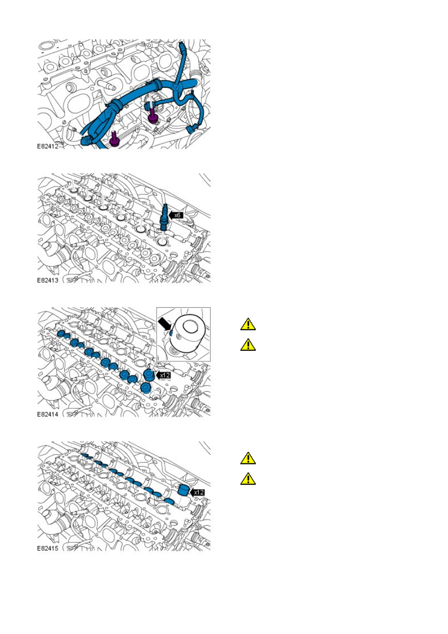
10. CAUTIONS:
Mark the components to aid installation.
Extreme cleanliness must be exercised when
handling these components.
Remove the 12 two-stage hydraulic lash adjusters.
10.
11. CAUTIONS:
Mark the components to aid installation.
Extreme cleanliness must be exercised when
handling these components.
Remove the 12 tappets.
11.