Frelander 2. Manual - part 155
Item
Part Number
Description
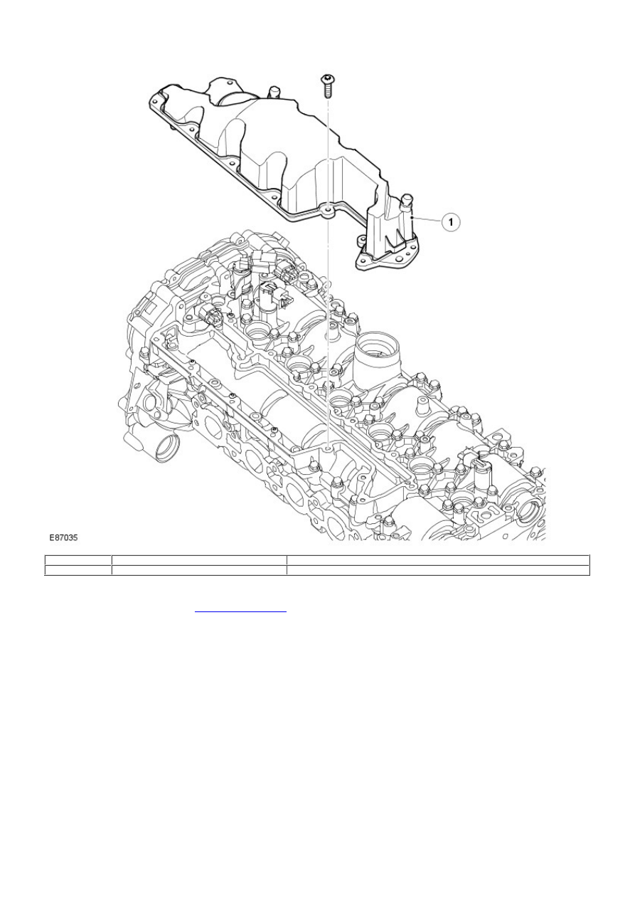
1
-
Oil separation housing
Crankcase gases are routed from the crankcase, engine block and cylinder head to the oil separation housing located on the
camshaft cover. From the oil separation housing, the crankcase gases are routed via a pressure regulator, located at the rear edge
of the housing, to the cylinder head and the intake ports for the intake valves.
For additional information, refer to:
Evaporative Emissions
(303-13 Evaporative Emissions, Description and Operation).
Camshaft Housing