Frelander 2. Manual - part 151


  Index      Land Rover     Land Rover Frelander 2 - service repair manual 2006-2010 year


Search            


Content   ..  149  150  151  152   ..


Frelander 2. Manual - part 151


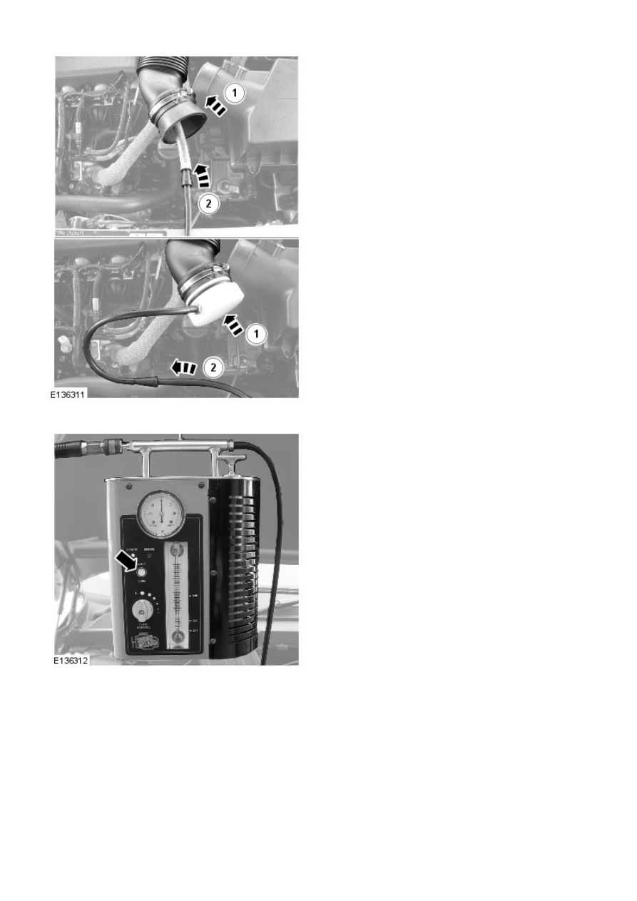
7. NOTE: Make sure the smoke test equipment adapter is a
good fit to the air cleaner outlet pipe. This must be an air
tight seal.

Connect the smoke test equipment supply hose to the air
cleaner outlet pipe.

1. Install the appropriate adapter to the air cleaner

outlet pipe.

2. Connect the smoke test equipment supply hose to

the adapter link hose.

8. NOTE: The flow control valve must be in the fully open
position.

• NOTE: Smoke is produced for 5 minutes. The smoke test
equipment will automatically switch off after this period of
time.

Switch the smoke test equipment on.

9. Remove the oil filler cap, and observe until a constant flow of

smoke is visible leaving the oil filler orifice. Install the oil filler
cap.

10. NOTE: The longer smoke is allowed to exit from a leak, the
more fluorescent dye will be deposited at a leak location.

Using the torch supplied in the kit set to white light, look for
escaping smoke. Alternatively, use the ultraviolet light to look
for fluorescent dye deposits at the source of a leak.

Engine - I6 3.2L Petrol -

Lubricants, Fluids, Sealers and Adhesives

Description

Land Rover Part No.

Cam cover to cylinder head joint

LR006801 (Loctite 510)

Bedplate to oil sump

STC50550

Block to bedplate

STC50550

Engine oil - NAS, Middle East and North Africa Models

5W/30 - ACEA A1 + ILSAC GF-3 or ILSAC GF-3*

Engine oil - ROW  Models

0W/30 - ACEA A5/B5

The recommended oil change interval for ILSAC GF-3 is 5000 miles.

Capacities

Item

Capacity (liters/pints/US

quarts)

Dry fill including filter

9.3/16.4/9.8

Service fill - includes filter

7.7/13.6/8.1

Amount of oil required to bring the level from the lower to the upper mark on the
dipstick

0.8/1.4/0.9

General Specification

Item

Specification

Type

3.2 liter, inline 6 naturally aspirated petrol engine, twin overhead
camshafts, 4 valves per cylinder

Cylinder arrangement

Inline 6

Cylinder numbering

1-6 from front of engine

Bore - nominal

84.0 mm (3.307 in)

Stroke

96.0 mm (3.779 in)

Capacity

3192 cm³ (195.8 in³)

Firing order

1 - 5 - 3 - 6 - 2 - 4

Compression ratio

10.8:1

Direction of rotation

Clockwise from front of engine

Maximum power

171 kW (230 hp) @ 6300rpm

Maximum torque

317 Nm (234 lb-ft) @ 3200rpm

Engine oil pressure*:
At 800 rev/min

1.03 bar/103 kPa/15 lb/in²

At 4000 rev/min

3.45 bar/345 kPa/50 lb/in²

Oil pump
Oil pump to crankshaft clearance

0.087mm ±0.022 mm (0.00343 in ± 0.000866 in)

Maximum permissible cylinder head warp:
Over head length

0.05 mm (0.00196 in)

Over head width

0.03 mm (0.00118 in)

Cylinder head height

149.4 mm ± 0.15 mm (5.882 in ± 0.0059 in)

Maximum permissible amount to be removed
during skimming

0.3 mm (0.0118 in)

Main bearing journals:
Number

7

Diameter standard

65 mm + 0.004 - 0.015 mm (2.55 in + 0.000157 - 0.000590 in)

Maximum diameter variation

0.006 mm (0.000236 in)

Big end journals:
Diameter standard

50 mm + 0.004 - 0.015 mm (1.96 in + 0.000157 - 0.000590 in)

Maximum diameter variation

0.01 mm (0.000393 in)

Camshaft:
Number of bearings

7 per camshaft

Tappets+:
Inlet

Hydraulic

Exhaust+

Graded

Valves:
Valve clearance - Exhaust

0.45mm ±0.05 mm (0.0177 in ± 0.00196 in)

Length - inlet valve

106.19 mm ± 0.07 mm (4.18 in ± 0.0275 in)

Length - exhaust valve

129.96 mm ± 0.07 mm (5.12 in ± 0.0275 in)

Seat angle

45° ± 0.01°

Head diameter - inlet valve

33 mm ± 0.15 mm (1.29 in ± 0.0590 in)

Head diameter - exhaust valve

28 mm ± 0.15 mm (1.10 in ± 0.0590 in)

Stem diameter - inlet valve

5.97 mm + 0 -.015 mm (0.235 in + 0 -000590 in)

Stem diameter - exhaust valve

5.962 mm +0 -0.007 mm (0.234 in +0 -0.000275 in)

Stem to guide clearance - inlet valve

50-70 µm

Stem to guide clearance - exhaust valve

50-70 µm

Valve springs:
Type

Conical

Length (free)

45 mm (1.77 in)

* Prior to checking the engine oil pressure, a road test of 6 miles (10 kilometres) must be carried out. Do not
attempt to attain normal engine operating temperature by allowing the engine to idle.

+ There are 50 different thicknesses of graded tappet available ranging from 2.950mm to 3.685 mm (0.116 in to
0.145 in) rising in increments of 0.015 mm (0.0005 in).

Torque Specifications

Description

Nm

lb-ft

Camshaft bearing housing to cylinder head bolts

A

A

Camshaft drive sprocket bolts
Exhaust

75 + 90°

55 + 90°

Inlet

110

81

Cylinder head bolts

A

A

Cylinder head wiring harness mounting bolts

6

5

Dipstick tube bolt

10

7

Engine insulator lower bolts

110

81

Engine insulator lower heatshield Torx screw

10

7

Engine insulator upper bolts

110

81

Engine mount bracket LH:
M8*

25

18

M12*

80

59

Engine mount LH bolts

175

129

Engine mount RH bolts

80

59

Engine mount bracket RH bolt:
M10*

45

33

M12*

80

59

Flywheel flexplate bolts

45 + 50°

33 + 50°

Exhaust manifold bolts

A

A

Intake manifold bolts

16

12

Lifting bracket bolts

48

35

Lower inlet manifold bolts

10

7

Lubricant drain plug

38

28

Oil cooler assembly to block retaining bolts

10

7

Oil cooler hose bolts

10

7

Oil filter

25

18

Oil level sensor bolt

8

6

Oil pan bolts:
M7

17

13

M10

45

33

Oil pump adjuster bolt

17

13

Oil pump lock adjuster sleeve bolt

8

6

Oil strainer pick-up assembly bolt

17

13

Oil squirt jet

6

5

Throttle body to block support bolt

10

7

Throttle body screws*

8

6

Timing chain tensioner bolt

10

7

Timing cover bolts

A

A

VVT solenoid

10

7

VVT unit retaining bolt

A

A

* New nuts/bolts must be fitted

A = refer to procedure for correct torque sequence

Engine - I6 3.2L Petrol - Engine

Description and Operation

EXTERNAL VIEW

OVERVIEW

The Si6 petrol engine is a 3.2 litre, inline 6-cylinder, naturally aspirated unit, with 4 valves per cylinder, operated by 2 overhead
camshafts. The engine emissions comply with EURO 4 (European Union emission regulations) and Ultra Low Emissions Vehicle
(ULEV) II legislative requirements and employs catalytic converters, electronic engine management control and pressure controlled
crankcase ventilation to limit the emission of pollutants. The cooling system is a low volume, high velocity system. The Engine


Content   ..  149  150  151  152   ..