Frelander 2. Manual - part 136
Item
Part Number
Description
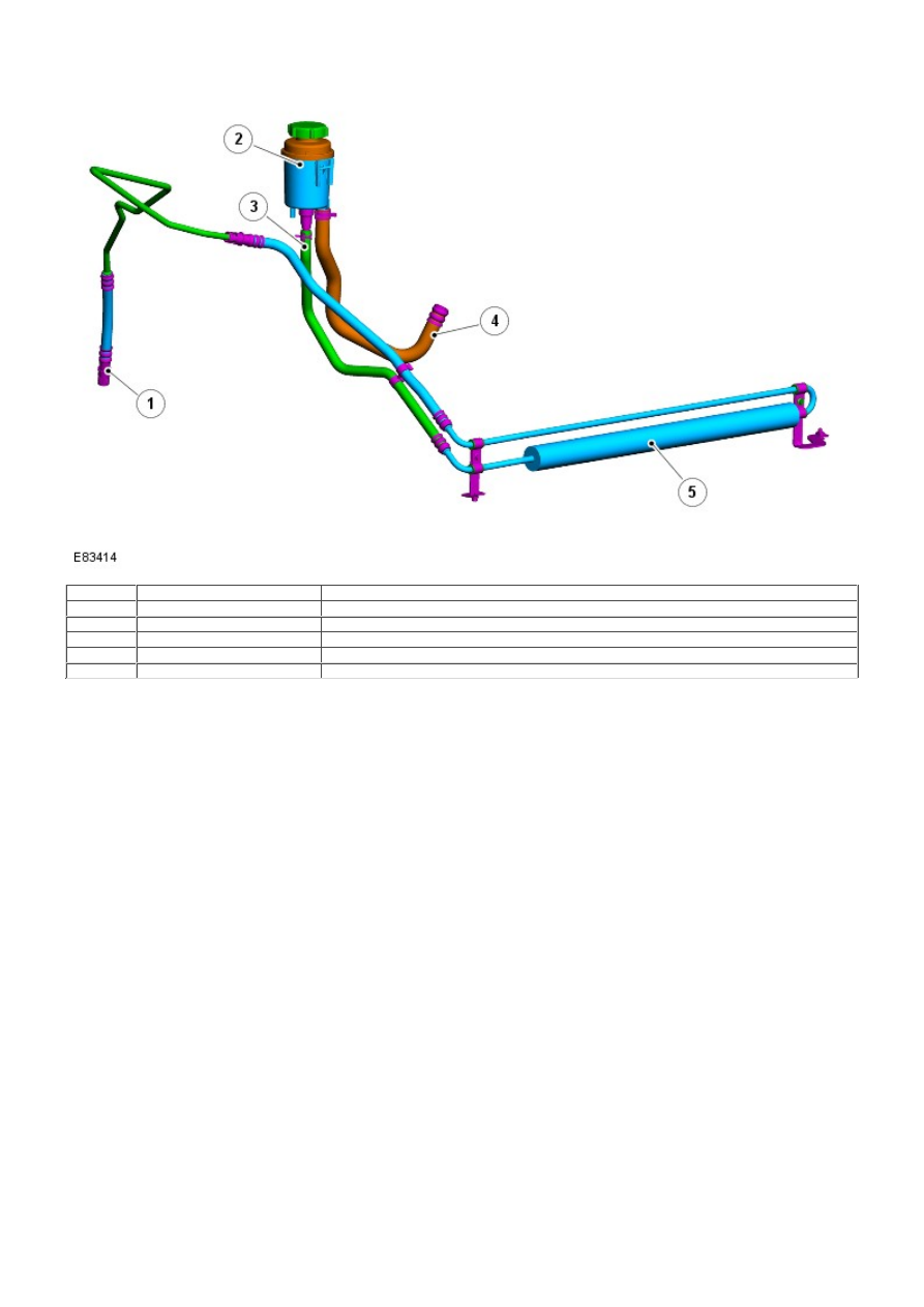
1
-
Fluid return (from steering gear)
2
-
Reservoir
3
-
Fluid return (from fluid cooler)
4
-
Suction hose (to power steering pump)
5
-
Fluid cooler
The fluid cooler is located in the return line from the steering gear to the reservoir. The cooler comprises flexible hoses
which connect between the reservoir and the return pipe from the steering gear. The cooler is an integral part of the hoses
and cannot be replaced as a separate component.
The cooler is a fabricated aluminum tube, through which the power steering fluid passes and is located in front of the
engine cooling radiator and the Air Conditioning (A/C) condenser. The outer diameter of the cooler tube has aluminum
loops attached to it which dissipate heat. Cool air entering the front of the vehicle passes over the cooler and flows
through the loops. The loops act as heat exchangers, conducting heat from the fluid as it passes through the tube.
PRINCIPLES OF OPERATION
Fixed Displacement Pump Schematic - Typical