Frelander 2. Manual - part 76
Bearing Rumble
Bearing rumble sounds like marbles being tumbled. This condition is usually caused by a worn/damaged wheel bearing.
The lower pitch is because the wheel bearing turns at only about one-third of the driveshaft speed. Wheel bearing noise
also may be high-pitched, similar to gear noise, but will be evident in all four driving modes.
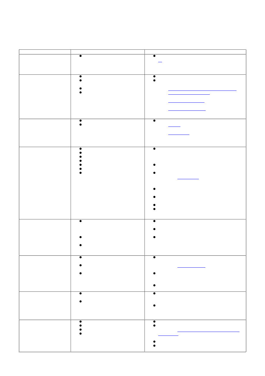
Symptom Chart
Symptom
Possible Cause
Action
Noise is at constant tone
over a narrow vehicle speed
range. Usually heard on
light drive and coast
conditions
Rear drive axle
For additional information. GO to Pinpoint Test
A.
Noise is the same on drive
or coast
Road noise
W orn or damaged driveshaft
joint
Driveshaft center bearing
W heel bearing
Normal condition (road noise)
Check and install new components a required.
REFER to:
Driveshaft - Vehicles Without: Diesel
Particulate Filter (DPF)
(205-01
Driveshaft, Removal and Installation),
Rear Wheel Bearing
(204-02 Rear
Suspension, Removal and Installation),
Front W heel Bearing
(204-01 Front
Suspension, Removal and Installation).
Noise is produced with the
vehicle stationary and
when driving
Engine
Transmission
For additional information. REFER to:
Engine
(303-00 Engine System - General
Information, Diagnosis and Testing),
Diagnostics
(307-01 Automatic
Transmission/Transaxle, Diagnosis and
Testing).
Loud clunk in the driveline
when shifting from reverse
to forward
Transmission calibration
Transmission Mount
Transmission
Suspension components
Backlash in the driveline
Engine idle speed set too high
Engine mount
Using the manufacturer approved diagnostic
system, re-configure the Transmission Control
Module (TCM) with the latest available
calibration
Inspect and install new transmission mounts
as required
For transmission diagnostics.
REFER to:
Diagnostics
(307-01 Automatic
Transmission/Transaxle, Diagnosis and
Testing).
Inspect and install new suspension
components as required
Inspect and install new driveline components
as required
Check and adjust the idle speed as required
Inspect and install new engine mounts as
required
Clicking, popping, or
grinding noises
Inadequate or contaminated
lubrication in the front/rear
drive halfshaft constant velocity
(CV) joint
Another component contacting
the front/rear drive halfshaft
W heel bearings, brakes or
suspension components
Inspect, clean and lubricate with new grease
as required
Ensure all other components are clear from
front/rear drive halfshaft
Inspect and install new components as
required
Vibration at highway
speeds
Out of balance wheel(s) or
tire(s)
Driveshaft misaligned/out of
balance
Driveshaft center bearing
touching body mounting point
Balance and install new wheel(s) and tire(s) as
required.
REFER to:
Wheel and Tire
(204-04 W heels and
Tires, Removal and Installation).
Check driveshaft alignment. Check driveshaft
balance using manufacturer approved
diagnostic system
Check driveshaft alignment
Shudder, Vibration During
Acceleration
Powertrain/driveline
misalignment
High constant velocity (CV) joint
operating angles caused by
incorrect ride height
Check for powertrain/driveline misalignment
and rectify as required. Install new
components as required
Check the ride height and verify the correct
spring rate. Install new components as
required
Lubricant Leak
Rear drive axle breather
Damaged seal
Rear drive axle filler plug
Rear drive axle cover/active
on-demand coupling joint
Check oil level and correct as necessary
Install new driveshaft/pinion seal as required.
REFER to:
Active On-Demand Coupling Drive
Pinion Seal
(205-02 Rear Drive
Axle/Differential, Removal and Installation).
Check and install new filler plug as required
Re-seal leaking joints as required