Frelander 2. Manual - part 23
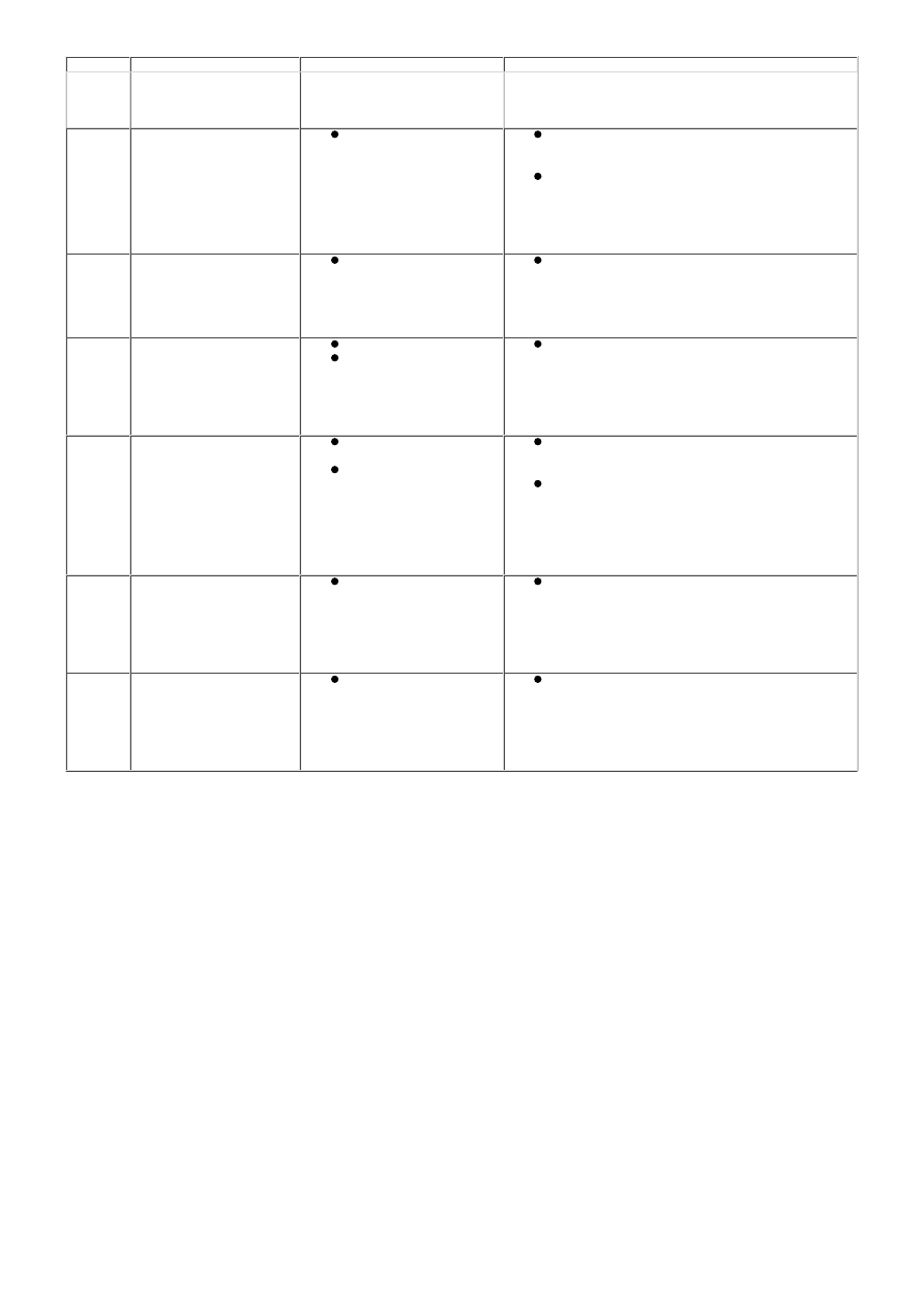
DTC
Description
Possible Cause
Action
prior approval programme is in operation, prior
to the installation of a new module/
component
U1A4C-00 Build / End of Line mode
Active - No sub type
information
Error/mismatch in car
configuration file
Using the manufacturer approved diagnostic
system check and up-date the car configuration
file as required. Clear the DTC and re-test
Check and install a new seat control module.
Refer to the warranty policy and procedures
manual, or determine if any prior approval
programme is in operation, prior to the
installation of a new module/ component
U3000-49 Control Module - Internal
electronic failure
Seat control module
internal failure
Check and install a new seat control module.
Refer to the warranty policy and procedures
manual, or determine if any prior approval
programme is in operation, prior to the
installation of a new module/ component
U3001-46 Control Module Improper
Shutdown - Calibration /
parameter memory failure
Event information
Seat control module
whilst in manufacturing
mode the power has
been disconnected
DTC for information only. Clear the DTC and
retest. If the problem persists, renew the
module. Refer to the warranty policy and
procedures manual, or determine if any prior
approval programme is in operation, prior to
the installation of a new module/ component
U3002-81 Vehicle Identification
Number - Invalid serial
data received
Error/mismatch in car
configuration file
The seat control
module has previously
been installed to
another vehicle
Using the manufacturer approved diagnostic
system check and up-date the car configuration
file as required. Clear the DTC and re-test
Check and install the original, or a new seat
control module. Refer to the warranty policy
and procedures manual, or determine if any
prior approval programme is in operation, prior
to the installation of a new module/
component
U3003-16 Battery Voltage – Circuit
voltage below threshold
Seat control module
supply voltage below
threshold
Check vehicle battery and charging system,
repair as required. Refer to the relevant section
in the workshop manual. Refer to the electrical
circuit diagrams and check the power and
ground supply circuits to the seat control
module. Clear the DTC and re-test
U3003-17 Battery Voltage – Circuit
voltage above threshold
Seat control module
supply voltage above
threshold
Check vehicle battery and charging system,
repair as required. Refer to the relevant section
in the workshop manual. Refer to the electrical
circuit diagrams and check the power and
ground supply circuits to the seat control
module. Clear the DTC and re-test