Freelander Body Repair Manual - part 65


  Index      Land Rover     Freelander Body Repair Manual 1998 year


Search            


Content   ..  63  64  65  66   ..


Freelander Body Repair Manual - part 65


PANEL REPAIRS

PROCEDURES

3

PANEL REPLACEMENT PROCEDURE

This procedure is designed to explain the basic
panel removal and replacement method. The main
criterion in removal and replacement of body panels
is that the original standard is maintained as far as
possible. While individual repairs will differ in detail,
this procedure has been devised placing emphasis
on ease of repair and the elimination of unnecessary
work.

Body panels are being increasingly manufactured in
high strength steels to meet design requirements for
safety and weight saving. As panels in high strength
steels cannot be visually identified, and as they are
more sensitive to excess heat than panels
manufactured from low carbon steel, it is advisable
that the following procedure be observed at all
times.

Remove panel

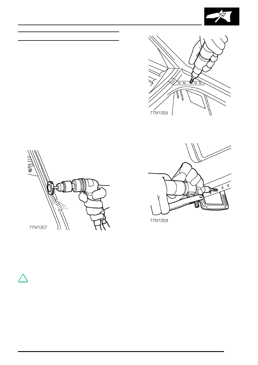
1. Expose resistance spot welds. For those spot

welds which are not obviously visible, use a
rotary impregnated wire brush fitted to an air
drill, or alternatively a hand held wire brush.

NOTE: In wheel arch areas it may be
necessary to soften underbody coating,
using a hot air gun, prior to exposing spot

welds.

2. Cut out welds using a cobalt drill.

3. Alternatively, use a clamp-type spot weld

remover.

PANEL REPAIRS

4

PROCEDURES

4. Cut away the bulk of the panel as necessary

using an air saw.

NOTE: On certain panel joints MIG welds
and braze should be removed using a
sander where possible, before cutting out

the panel bulk.

5. Separate spot welded joints and remove panel

remnants using hammer, bolster chisel and
pincers.

Prepare old surfaces

1. Remove any remaining sealant using a hot air

gun to minimise the risk of toxic fumes caused
by heat generated during welding.

CAUTION: CARE MUST BE TAKEN TO
AVOID EXCESSIVE HEAT BUILD-UP
WHEN USING THE HOT AIR GUN.

2. Clean all panel joint edges to a bright smooth

finish, using a belt-type sander.

NOTE: As an alternative, a disc sander
may be used.

3. Straighten existing panel joint edges using

shaping block and hammer.

PANEL REPAIRS

PROCEDURES

5

Prepare new surfaces

1. Mark out bulk of new panel and trim to size,

leaving approximately 50mm overlap with
existing panel. Offer up new panel/section,
align with associated panels (e.g. new rear
quarter aligned with door and tailgate). Clamp
into position.

2. Cut new and existing panels as necessary to

form butt, joggle or brace joint as required.
Remove all clamps and metal remnants.

3. Prepare new panel joint edges for welding by

sanding to a bright finish. This must include
inner as well as outer faces.

4. Apply suitable weld-through primer, to panel

joint surfaces to be welded, using brush or
aerosol can.

PANEL REPAIRS

6

PROCEDURES

5. Apply seam sealer or structural adhesive, as

applicable, to panel joint surfaces.

See

INFORMATION, Sealing and corrosion
protection.

Offer up and align

Offer up new panel and align with associated
panels. Clamp into position using welding clamps or
Mole grips. Where a joggle or brace joint is being
adopted, make a set in the original panel joint edge
or insert a brace behind the joint.

NOTE: In cases where access for welding
clamps is difficult, it may be necessary to
use tack welds.

Welding

1. Select arms for resistance spot welding and

shape electrode tips using a tip trimmer.

CAUTION: Use arms not exceeding
300mm in length.

NOTE: To maintain efficiency, the tips will
require regular cleaning with emery cloth.

2. Fit resistance spot welding arms and test

equipment for satisfactory operation, using test
coupons. Where monitoring equipment is not
available, verify weld strength by checking that
metal around the weld puddle pulls apart under
tension during pulling.


Content   ..  63  64  65  66   ..