Freelander 1. Manual - part 185


  Index      Land Rover     Freelander 1 - service manual 2002 year


Search            


Content   ..  183  184  185  186   ..


Freelander 1. Manual - part 185


REAR SUSPENSION

REPAIRS

64-3

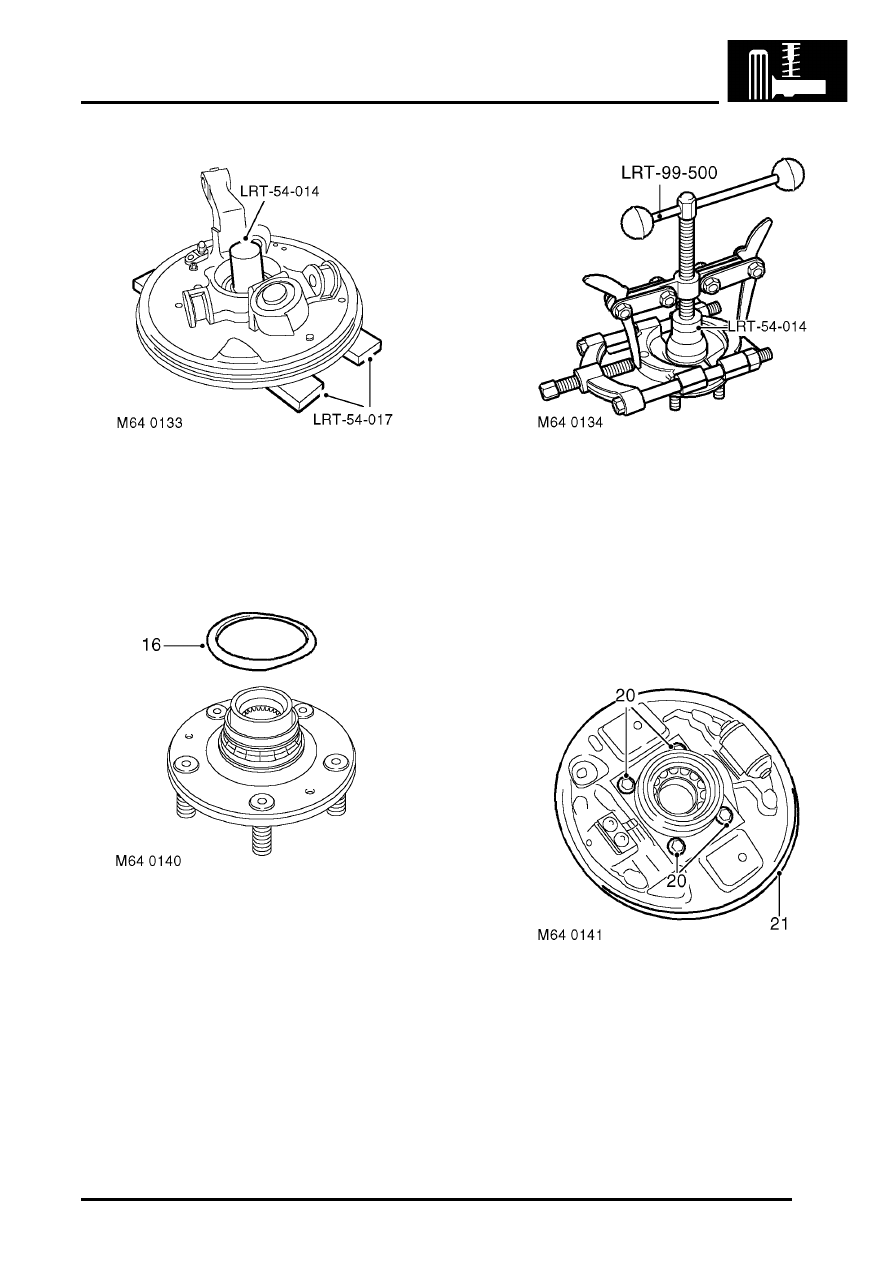
14. Position hub assembly to press, support on 

tools LRT-54-017 and press out drive flange 
using tool LRT-54-014.

NOTE: Outer bearing track will remain on drive 
flange.

15. Remove bearing sealing plate from inner track.
16. Position drive flange in a vice.

17. Clamp both halves of a suitable bearing 

separator around inner track ensuring that 
inner lip fits in groove on inner track.

From 2002MY the groove in the inner track was 
deleted. To remove the inner track, clamp the 
separator around the inner track bearing 
surface.

18. Using tool LRT-99-500 and thrust pad LRT-54-

014 withdraw inner track from drive flange.

19. Fit hub to vice and remove 4 bolts securing 

backplate to hub.

20. Remove backplate.

REAR SUSPENSION

64-4

REPAIRS

21. Remove circlip from bearing.

22. Position hub to press and press out bearing 

using tool LRT-54-015 and LRT-54-017
discard bearing.

CAUTION: Never re-use existing bearing.

Refit

1. Clean hub and drive flange.

2. Support hub on tool LRT-54-016 and press in 

new bearing using LRT-54-015. 

3. Fit circlip to hub.
4. Fit hub to vice, fit backplate and tighten bolts to 

45 Nm (33 lbf.ft).

5. Support bearing on tool LRT-54-015 and press 

drive flange into bearing using LRT-54-014. 

6. Fit hub assembly to drive shaft.
7. Fit hub to damper and tighten bolts to 205 Nm 

(151 lbf.ft).

CAUTION: Nuts and bolts must be tightened 
with weight of vehicle on suspension.

8. Fit nut, bolt and washers securing transverse 

links to hub and tighten nut to 105 Nm (77 lbf.ft).

REAR SUSPENSION

REPAIRS

64-5

9. Fit trailing link to hub and tighten nut and bolt to 

120 Nm (89 lbf.ft).

NOTE: Ensure that washers are fitted to both 
ends of bolts

10. Clean ABS sensor, smear sensor with an anti-

seize grease and fit sensor to hub.

CAUTION: Ensure ABS sensor is fully 
located into hub, so that sensor touches 
pole wheel teeth.

11. Fit brake pipe to wheel cylinder and tighten 

union to 14 Nm (10 lbf.ft).

12. Fit clip securing brakepipe to bracket.
13. Fit and secure handbrake cable to backplate.
14. Fit brake shoes.


 + 

 BRAKES, REPAIRS, Brake Shoes - 

rear set.

15. Fit new drive shaft nut and  tighten to 400 Nm 

(295 lbf.ft). Stake nut to shaft. 

16. Bleed brakes.


 + 

 BRAKES, ADJUSTMENTS, Brake 

bleed.

17. Fit road wheel(s) and tighten nuts to 115  Nm 

(85 lbf.ft).

18. Remove stands and lower vehicle.

Damper 

$% 64.30.02

Remove

1. Raise rear of vehicle.

WARNING: Do not work on or under a 
vehicle supported only by a jack. Always 
support the vehicle on safety stands.

2. Remove road wheel.
3. Clamp brake hose to prevent fluid loss.
4. Position absorbent cloth to catch spillage.

5. Loosen brake pipe union to hose and release 

union.

CAUTION: Always fit plugs to open 
connections to prevent contamination.

6. Remove clip securing brake hose to bracket on 

damper. Release brake hose from bracket.

7. Release ABS sensor harness and brake hose 

from damper.

8. Release ABS sensor from hub.

REAR SUSPENSION

64-6

REPAIRS

9. Remove 2 nuts and bolts securing hub to 

damper.

10. Release damper from hub.
11. Remove rear quarter lower casing.


 + 

 INTERIOR TRIM COMPONENTS, 

REPAIRS, Trim casing - rear quarter - lower 
- 3 door.
 

 + 

 INTERIOR TRIM COMPONENTS, 

REPAIRS, Trim casing - rear quarter - lower 
- 5 door.

12. Remove 3 nuts from damper top mounting and 

remove spring and damper assembly.

13. Remove rubber seal from top mounting.

14. Position a suitable spring compressor in vice.

CAUTION: Note alignment of top mounting, 
spring and damper dust cover.

15. Position spring and damper assembly to spring 

compressor. Compress spring. 

16. Reference mark between top mounting and 

spring.


Content   ..  183  184  185  186   ..