Freelander 1. Manual - part 110


  Index      Land Rover     Freelander 1 - service manual 2002 year


Search            


Content   ..  108  109  110  111   ..


Freelander 1. Manual - part 110


ENGINE MANAGEMENT SYSTEM - SIEMENS

REPAIRS

18-3-5

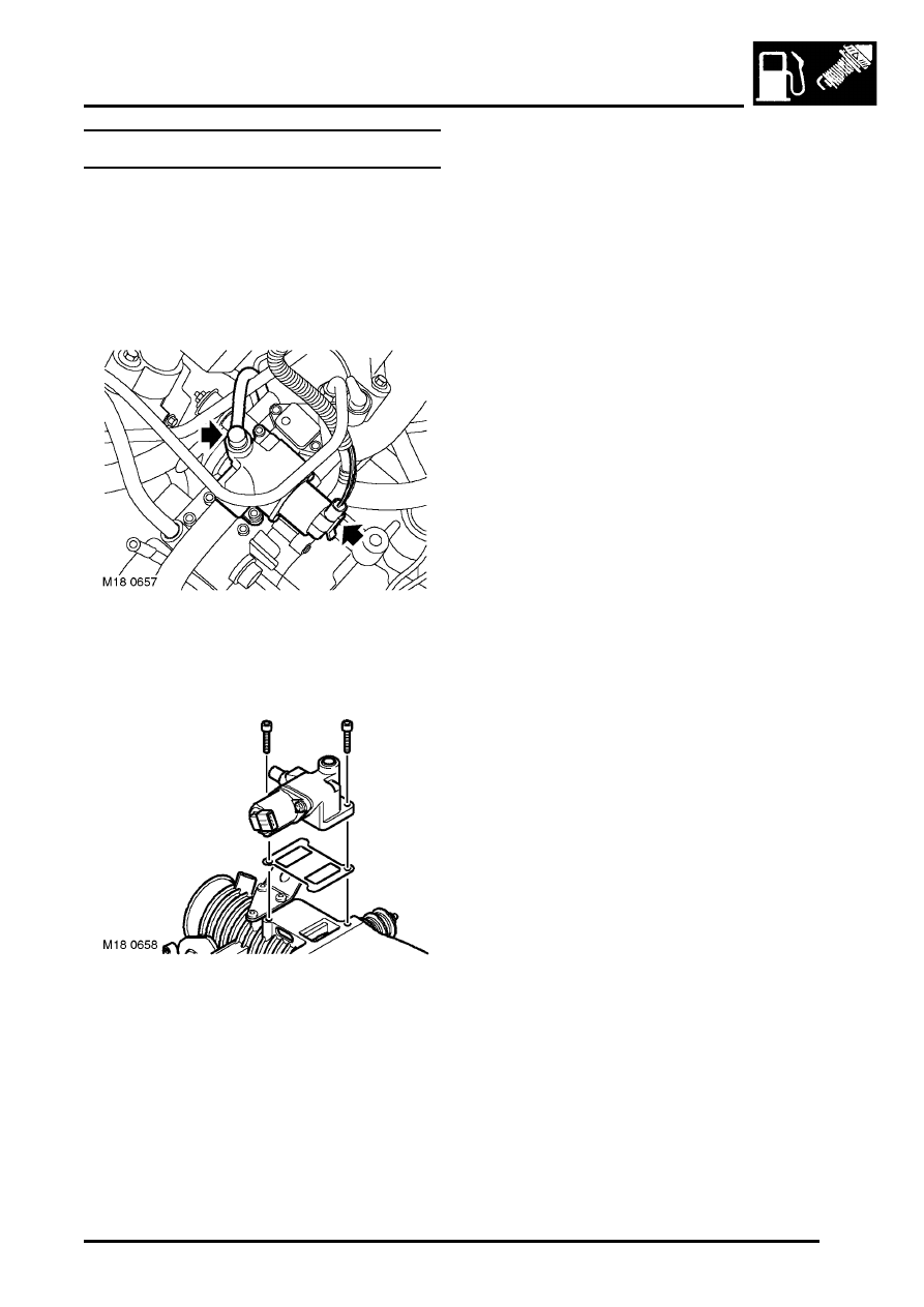
Idle Air Control Valve (IACV) 

$% 18.30.05

Remove

1. Disconnect battery earth lead.
2. Remove engine acoustic cover.


 + 

 ENGINE - K SERIES KV6, REPAIRS, 

Cover - engine acoustic.

3. Disconnect multiplug from IACV.
4. Depress locking collar and release vacuum 

hose from IACV housing.

5. Remove 2 Allen bolts securing IACV to throttle 

body.

6. Remove IACV and discard gasket.

Refit

1. Clean mating faces of IACV and throttle body.
2. Fit new gasket to IACV.
3. Position IACV to throttle body, fit and tighten 

Allen bolts.

4. Connect vacuum hose to IACV.
5. Connect multiplug to IACV.
6. Fit engine acoustic cover.


 + 

 ENGINE - K SERIES KV6, REPAIRS, 

Cover - engine acoustic.

7. Connect battery earth lead.

ENGINE MANAGEMENT SYSTEM - SIEMENS

18-3-6

REPAIRS

Sensor - intake air temperature (IAT) - 
NAS 

$% 18.30.09

Remove

1. Disconnect multiplug from IAT sensor.
2. Release clip and remove IAT sensor. Discard 

seal.

Refit

1. Clean IAT sensor and mating face.
2. Fit new seal to sensor.
3. Fit IAT sensor and connect multiplug.

Sensor - engine coolant temperature 
(ECT) 

$% 18.30.10

Remove

1. Disconnect battery earth lead.
2. Remove thermostat.


 + 

 COOLING SYSTEM - K SERIES KV6, 

REPAIRS, Thermostat.

3. Disconnect multiplug from coolant temperature 

sensor.

4. Remove coolant temperature sensor and 

discard sealing washer.

5. Remove coolant temperature sensor from 

cylinder block.

6. Remove steel shim and sealing washer from 

temperature sensor, discard sealing washer.

Refit

1. Clean coolant temperature sensor and mating 

face on cylinder block.

2. Fit new sealing washer, then steel shim to 

coolant temperature sensor.

3. Position coolant temperature sensor and 

tighten to 17 Nm (12.5 lbf.ft).

4. Fit thermostat.


 + 

 COOLING SYSTEM - K SERIES KV6, 

REPAIRS, Thermostat.

5. Connect battery earth lead.

ENGINE MANAGEMENT SYSTEM - SIEMENS

REPAIRS

18-3-7

Sensor - crankshaft position (CKP) 

$% 18.30.12

Remove

1. Disconnect battery earth lead.
2. Remove engine acoustic cover.


 + 

 ENGINE - K SERIES KV6, REPAIRS, 

Cover - engine acoustic.

3. Disconnect CKP sensor multiplug from engine 

harness.

4. Remove underbelly panel.


 + 

 EXTERIOR FITTINGS, REPAIRS, 

Panel - underbelly.

5. Remove bolt securing CKP sensor to gearbox 

housing and remove sensor.

Refit

1. Clean CKP sensor and mating face.
2. Position CKP sensor, fit and tighten bolt to 9 

Nm (6.5 lbf.ft).

3. Fit underbelly panel.


 + 

 EXTERIOR FITTINGS, REPAIRS, 

Panel - underbelly.

4. Connect CKP sensor multiplug to engine 

harness.

5. Fit engine acoustic cover.


 + 

 ENGINE - K SERIES KV6, REPAIRS, 

Cover - engine acoustic.

6. Connect battery earth lead.

ENGINE MANAGEMENT SYSTEM - SIEMENS

18-3-8

REPAIRS

Sensor - throttle position (TP)

$% 18.30.17

Remove

1. Disconnect battery earth lead.
2. Remove acoustic cover.


 + 

 ENGINE - K SERIES KV6, REPAIRS, 

Cover - engine acoustic.

3. Disconnect multiplug from TP sensor.

4. Remove and discard 2 Torx screws and wave 

washers securing TP sensor to inlet manifold.

5. Remove TP sensor specification plate.

6. Pull TP sensor from throttle spindle.

CAUTION: Do not twist or apply leverage to 
throttle position sensor.

Refit

1. Clean mating faces of throttle housing and TP 

sensor.

2. Fit TP sensor to throttle spindle. Ensure that 

during fitting the machined flat on the throttle 
spindle is aligned with the mating portion of the 
TP sensor

CAUTION: The throttle position sensor can 
be easily damaged during fitting. When 
pressing the sensor onto the throttle 
spindle, use fingers only, and only apply 
pressure to the area shown shaded in the 
illustration.

3. Rotate TP sensor in an anti-clockwise direction 

to align fixing holes.

CAUTION: Do not rotate throttle position 
sensor in a clockwise direction and ensure 
that it is not rotated beyond its internal 
stops.

4. Fit TP sensor specification plate.

M18 0695


Content   ..  108  109  110  111   ..