Freelander 1. Manual - part 96


  Index      Land Rover     Freelander 1 - service manual 2002 year


Search            


Content   ..  94  95  96  97   ..


Freelander 1. Manual - part 96


ENGINE - K SERIES KV6

OVERHAUL 12-3-75

Refit

1. Fit oil pump gasket.


 + 

 ENGINE - K SERIES KV6, 

OVERHAUL, Oil pump.

2. Fit engine sump.


 + 

 ENGINE - K SERIES KV6, 

OVERHAUL, Sump - engine oil.

3. Fit crankshaft rear oil seal.


 + 

 ENGINE - K SERIES KV6, 

OVERHAUL, Crankshaft rear oil seal.

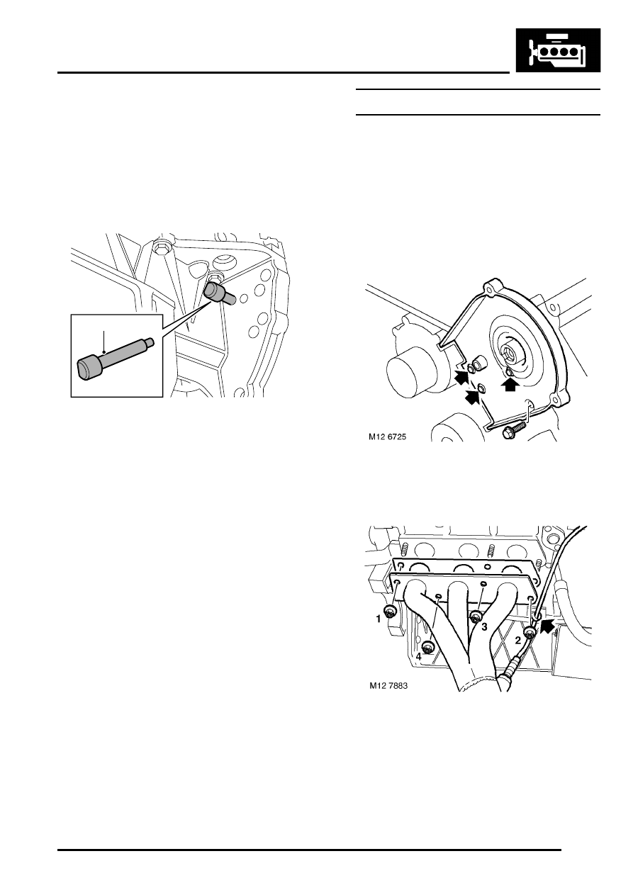
4. Rotate crankshaft until timing pin LRT-12-232 

can be inserted through hole immediately 
adjacent to side of lower crankcase and into 
elongated hole in drive plate.

CAUTION: Ensure that pin is in elongated 
hole. Do not use cast arrow on oil pump 
body as a timing mark. Do not remove 
timing pin until timing belts are fitted.

5. Fit cylinder head gaskets.


 + 

 ENGINE - K SERIES KV6, 

OVERHAUL, Cylinder head gasket - LH.
 

 + 

 ENGINE - K SERIES KV6, 

OVERHAUL, Cylinder head gasket - RH.

Cylinder head gasket - LH

$% 12.29.02.01

Remove

1. Remove and discard camshaft timing belt.


 + 

 ENGINE - K SERIES KV6, 

OVERHAUL, Camshaft timing belt.

2. Remove inlet manifold chamber.


 + 

 MANIFOLDS & EXHAUST SYSTEMS 

- K SERIES KV6, OVERHAUL, Gasket(s) - 
manifold chamber.

3. Remove 4 bolts securing LH front camshaft 

timing belt cover backplate to cylinder head and 
remove backplate.

4. Release HO2S lead from clip on cylinder block. 
5. Using sequence shown, loosen then remove 4 

nuts securing exhaust manifold to cylinder 
head. Remove manifold, remove and discard 
gasket.

6. Remove LH camshaft cover.


 + 

 ENGINE - K SERIES KV6, REPAIRS, 

Camshaft cover gasket - LH.

LRT-12-232

M12 7927

ENGINE - K SERIES KV6

12-3-76 OVERHAUL

7. Release clip and disconnect coolant bleed 

hose from LH inlet manifold, position hose 
aside.

8. Depress locking collar and release breather 

hose from LH inlet manifold.

9. Release clips securing RH injector harness to 

injector protection cover - if fitted, or from 
bosses on fuel rail.

10. Remove 2 bolts securing protection cover - if 

fitted and RH fuel rail to RH inlet manifold, 
remove cover.

11. Remove 2 bolts securing fuel rail to LH inlet 

manifold.

12. Release injectors from manifolds and carefully 

lay fuel rail and injectors aside.

CAUTION: Always fit plugs to open 
connections to prevent contamination.

ENGINE - K SERIES KV6

OVERHAUL 12-3-77

13. Using sequence shown, progressively loosen 

and remove 8 cylinder head bolts.

14. Remove cylinder head.

CAUTION: Support both ends of cylinder 
head on blocks of wood.

15. Remove and discard cylinder head gasket.

CAUTION: Do not rotate crankshaft with RH 
cylinder head fitted.

16. Remove and discard 2 cylinder head locating 

dowels.

NOTE: Replacement dowels are supplied with 
new cylinder head gasket.

17. Fit cylinder liner clamps LRT-12-144 and 

secure with cylinder head bolts.

CAUTION: Ensure that feet of clamps do not 
protrude over bores.

Refit

1. Clean cylinder head face.

CAUTION: Use suitable gasket removal 
spray and a plastic scraper.

2. Remove bolts securing cylinder liner clamps 

LRT-12-144 to cylinder block and remove 
clamps.

CAUTION: Do not rotate crankshaft.

3. Clean cylinder block face and dowel holes.
4. Clean cylinder head bolts and wipe dry.
5. Lightly lubricate threads and beneath heads of 

cylinder head bolts with clean engine oil.

6. Fit 2 new locating dowels supplied with 

replacement cylinder head gasket.

7. Check that fitted height of dowels is between 10 

to 11 mm (0.40 to 0.43 in) above cylinder block 
top face.

8. Fit new cylinder head gasket onto cylinder 

block with the word 'TOP' uppermost.

9. With assistance, fit cylinder head and carefully 

position LH inlet to RH inlet manifold.

10. Carefully enter cylinder head bolts, DO NOT 

DROP. Screw bolts into place by hand.

ENGINE - K SERIES KV6

12-3-78 OVERHAUL

11. Tighten cylinder head bolts progressively in the 

sequence shown to:

l

Stage 1 - 25 Nm (18 lbf.ft)

l

Stage 2 - 25 Nm (18 lbf.ft)

l

Stage 3 - 25 Nm (18 lbf.ft)

l

Stage 4 - Using an angle torque gauge, 
tighten a bolts in same sequence a further 
180

°

12. Fit LH camshaft cover gasket.


 + 

 ENGINE - K SERIES KV6, REPAIRS, 

Camshaft cover gasket - LH.

13. Remove and discard 'O' rings from injectors.
14. Clean injectors and injector locations in fuel rail.
15. Lubricate new 'O' rings with castor oil and fit to 

injectors.

16. Position fuel rail assembly and secure injectors 

to inlet manifolds.

17. Position injector protection cover - if fitted to RH 

fuel rail and secure injector harness to 
protection cover or fuel rail with clips.

18. Fit bolts securing fuel rail to inlet manifolds and 

tighten to 9 Nm (7 lbf.ft).

19. Connect coolant bleed hose to inlet manifold 

and secure with clip.

20. Connect breather hose to LH inlet manifold.
21. Position ignition coils to LH inlet manifold.
22. Position earth lead, fit nuts and bolts securing 

ignition coils to LH inlet manifold and tighten to 
9 Nm (7 lbf.ft).

23. Clean camshaft drive belt cover backplate bolts 

and apply Loctite 242 to first 3 threads.

24. Position backplate, fit and tighten bolts to 9 Nm 

(7 lbf.ft).

25. Clean exhaust manifold and cylinder head 

mating face.

26. Fit new exhaust manifold gasket. Position 

exhaust manifold, fit nuts and using sequence 
shown, tighten to 45 Nm (33 lbf.ft).

27. Secure HO2S lead in clip on cylinder block.
28. Connect HO2S multiplug and secure to support 

bracket.

29. Fit new camshaft timing belt.


 + 

 ENGINE - K SERIES KV6, 

OVERHAUL, Camshaft timing belt.


Content   ..  94  95  96  97   ..